4 - 10
79
81
83
84
86–89
90
91
93–96
99
Outputs the VCO circuit select signal.
High : The VCO circuit oscillates
203.95–263.945 MHz signal.
Outputs the VHF VCO select signal.
High : The VHF VCO’s power supply
(Q6, Q8) is ON.
Outputs the PLL loop control signal.
Input port for the PLL unlock signal.
High : While the loop is unlocked.
Input ports for the initial matrix signals.
Outputs the PLL data signal to the PLL
ICs (IC1, IC2).
Outputs the PLL clock signal to the
PLL ICs (IC1, IC2).
Output the initial matrix strobe signals
Outputs the wide/narrow FM select
signal.
Low : While selected narrow FM.
VCO_SHIFT
V_VCO
PLLSW
UNLK
MATRIX_
IN1–IN4
PLLDATA
PLLCK
OUT1–OUT4
WN_SEL
Pin Port
Description
number name
(MAIN unit; IC505)–Continued
2–4
5
6
7
8
9
12
13
18
Output the VHF bandpass filter track-
ing signals.
Outputs the UHF bandpass filter track-
ing signal.
Outputs the receiving attenuator con-
trol signal.
Outputs the bandpass filter shift con-
trol signal.
Low : While receiving 450–629.995
MHz.
Outputs the VHF output power control
signal.
Outputs the UHF output power control
signal.
Outputs the 800 MHz bandpass filter
tracking signal.
Outputs the reference frequency con-
trol signal.
Outputs the excess current detecting
signal.
TUNE_V1–V3
TUNE_U
ATT
BSHIFT
PCON_V
PCON_U
TUNE_8
REF_CON
REF_V
Pin Port
Description
number name
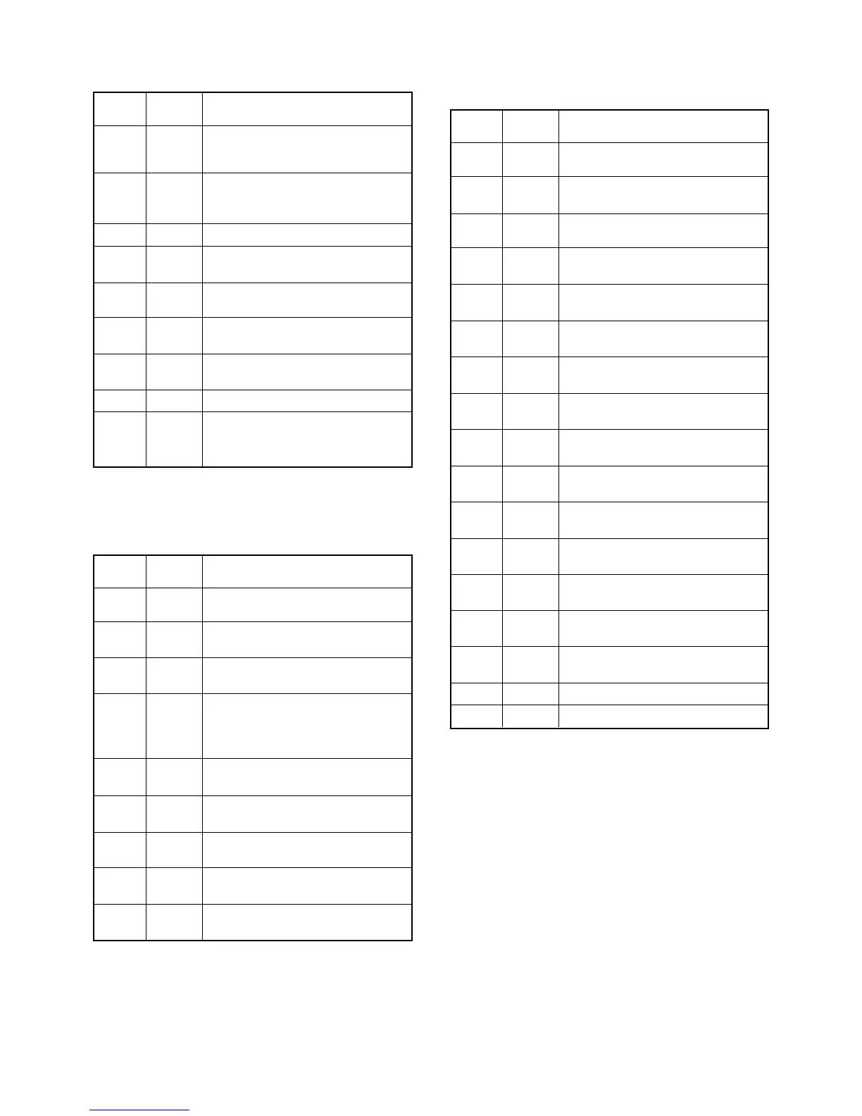
4-6-2 D/A CONVERTER IC PORT ALLOCATIONS
(MAIN UNIT; IC11)
1
3
4
5
6
7
8
24
25
30
31
39–42
43–78
83
86
88
89
Input port for the [BAND] key.
Low : The [BAND] key is pushed.
Outputs the umber LED control signal.
High : The LED lights ON.
Input port for the [S.MW] key.
Low : The [S.MW] key is pushed.
Input port for the [TONE] key.
Low : The [TONE] key is pushed.
Input port for the [LOW] key.
Low : The [LOW] key is pushed.
Input port for the [MONI] key.
Low : The [MONI] key is pushed.
Input port for the [SET] key.
Low : The [SET] key is pushed.
Input port for the [M/CALL] key
Low : The [M/CALL] key is pushed.
Input port for the [V/MHz] key.
Low : The [V/MHz] key is pushed.
Input port for the main dial’s A phase
signal.
Input port for the main dial’s B phase
signal.
Output the common signals to the LCD
(DS1).
Output the segment signals to the LCD
(DS1).
Outputs the green LED control signal.
High : The LED lights ON.
Input port for the [PWR] key.
Low : The [PWR] key is pushed.
Input port for the [VOL] controller.
Input port for the [SQL] controller.
4-6-3 FRONT CPU PORT ALLOCATIONS
(CONTROL UNIT; IC6)
BAND
A_LED
SMW
TONE
LOW
MONI
SET
M/CALL
VMHz
DIAL_A
DIAL_B
COM4–COM1
SEG1–SEG36
G_LED
PWR
VOL
SQL
Pin Port
Description
number name
 Loading...