4 - 1
4-1 RECEIVER CIRCUITS
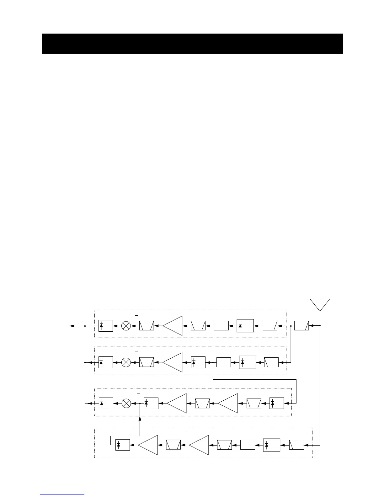
4-1-1 DUPLEXER CIRCUIT (MAIN UNIT)
The transceiver has a duplexer (low-pass and high-pass fil-
ters) on the first stage from the antenna connector to sepa-
rate the signals into VHF, UHF and above 800 MHz signals.
The 2 of low-pass filters (L51, L52, L56, C295, C299 and
L45, L46, L49, C282, C285, C289) are for VHF signals, the
low-pass (L51, L52, L56, C295, C299) and high-pass (L47,
L50, C284, C288, C292, C586) filters are for UHF signals
and high-pass filter (L55, L58, C298, C302, C304) is for
above 800 MHz signals.
The separated signals are applied to each antenna switch-
ing circuits (except SHF signals).
4-1-2 ANTENNA SWITCHING CIRCUITS
(MAIN UNIT)
The antenna switching circuit functions as a low-pass filter
while receiving. However, its impedance becomes very high
while transmitting by turning ON diode (VHF: D47, D49,
D50; UHF: D46, D48, D51). Thus transmit signals are
blocked from entering the receiver circuits. The antenna
switching circuit employs a 1/4λ type diode switching sys-
tem.
SHF signals pass through the RX switching circuit (D44).
The passed signals are then applied to the each attenuator
circuits.
4-1-3 ATTENUATOR CIRCUITS (MAIN UNIT)
The attenuator circuit attenuates the signal strength to a
maximum of 10 dB to protect the RF amplifier from distortion
when excessively strong signals are received.
The signals from the antenna switching circuit pass through
the each attenuator circuit (for VHF is D49 and D50, for UHF
is D46 and D48, for SHF is D39).
The D/A converter outputs “ATT” signal (IC11, pin 6), and is
then applied to the attenuator controller circuit (Q44). The
circuit output attenuator control signals to each attenuator
circuits.
The attenuated signals are applied to the each RF circuits.
4-1-4 RF CIRCUITS (MAIN UNIT)
The RF circuit amplifies signals within the range of frequen-
cy coverage and filters out-of-band signals.
• VHF RF CIRCUIT (118 MHz–174 MHz)
The signals from the attenuator circuit pass through the tun-
able bandpass filter (D41, L40, L44, C273, C280). The fil-
tered signals are amplified at the VHF RF amplifier (Q38)
and are then enter another 3-stage tunable bandpass filter
(D22, D23, D29, L28, C171, C174, C176, C177, C181,
C185, C191, C198, C204, C208) to suppress unwanted sig-
nals and improve the selectivity. The filtered signals are
applied to the VHF 1st mixer circuit (Q32).
• UHF RF CIRCUIT (430 MHz–440 MHz)
The signals from the attenuator circuit are applied to the
UHF RX switching circuit (D42). The signals are amplified at
the UHF RF amplifier (Q39) and are then enter bandpass fil-
ter (FI4) to suppress unwanted signals. The filtered signals
are applied to the UHF 1st mixer circuit (Q35).
SECTION 4 CIRCUIT DESCRIPTION
 Loading...