4 - 1
SECTION 4
CIRCUIT DESCRIPTION
4-1 RECEIVER CIRCUITS
4-1-1 RF SWITCHING CIRCUIT
(CTRL, RF AND PA UNITS)
The RF switching circuit leads receive signals to bandpass
filters from an antenna connector while receiving. However,
the circuit leads the signal from the RF power amplifier to the
antenna connector while transmitting.
RF signals (on HF/6 m bands) from [ANT 1] or [ANT 2] pass
through the antenna selector (CTRL unit; RL3), tuner switch-
ing relays (CTRL unit; RL1, RL2), transmit/receive switching
relay (CTRL unit; RL4), and low-pass filter (CTRL unit; L27,
L28, L35, C63–C67, C105, C115–C117), and are then ap-
plied to the RF unit via J2 (P2).
The signals from the CTRL unit bypass or pass through the
20 dB attenuator (RF unit; RL1, R1, R2). By selecting the at-
tenuator, 0 (bypass) and 20 dB attenuations are obtained.
The signals are then applied to the RF filters.
While operating on the 144 MHz band, the RF signals from
the [144 MHz ANT] are passed through the low-pass filter
(PA unit; L601–L603, C602, C604–C609) and transmit/re-
ceive switching relay (PA unit; RL601), then applied to the
RF unit via J601 (P601).
4-1-2 RF FILTER CIRCUIT (RF UNIT)
The RF filter circuit contains 8 bandpass and 2 low-pass fil-
ters. Bandpass filters pass only the desired band signals and
suppress any undesired band signals.
(1) 0.03–1.6 MHz
The signals are applied to the attenuator and low-pass filter
directly (see above at right).
(2) 1.6–60 MHz
The signals pass through the high-pass filter (L2–L4, C4–C7)
to suppress excessively strong signals below 1.6 MHz. The
filtered signals are applied to a low-pass or one of 8 band-
pass filters (see above at right).
(3) 108–174 MHz
The 144 MHz band signals are bypassed or passed through
the attenuator (R122), then applied to the tunable bandpass
filter (see above at right).
The filtered signals are applied to the pre-amplifier circuit.
4-1-3 PRE-AMPLIFIER CIRCUITS (RF UNIT)
Atotal of 3 pre-amplifier circuits are employed in this
transceiver. 2 for HF/6 m bands and 1 for 144 MHz band
operation.
When the pre-amplifier operation is turned OFF, the RF sig-
nals bypass this circuit.
When [P.AMP1] is selected, the filtered signals are applied
to the pre-amplifier 1 circuit (Q181, Q182), which has 10 dB
gain for the 1.8–54 MHz range, and when [P.AMP2] is se-
lected, the signals are applied to the pre-amplifier 2 circuit
(IC191), which has 16 dB gain for the 21–60 MHz range. The
pre-amplified signals are applied to the 60 MHz cut-out low-
pass filter (L210–L212, C211–215, C234).
During 144 MHz band operation, the filtered signals are pre-
amplified at the VHF pre-amplifier (Q502) when the [P.AMP]
is turned ON, and passed through the tunable bandpass filter
(D502–D504, L503–L504).
The filtered signals are applied to the 1st mixer circuit.
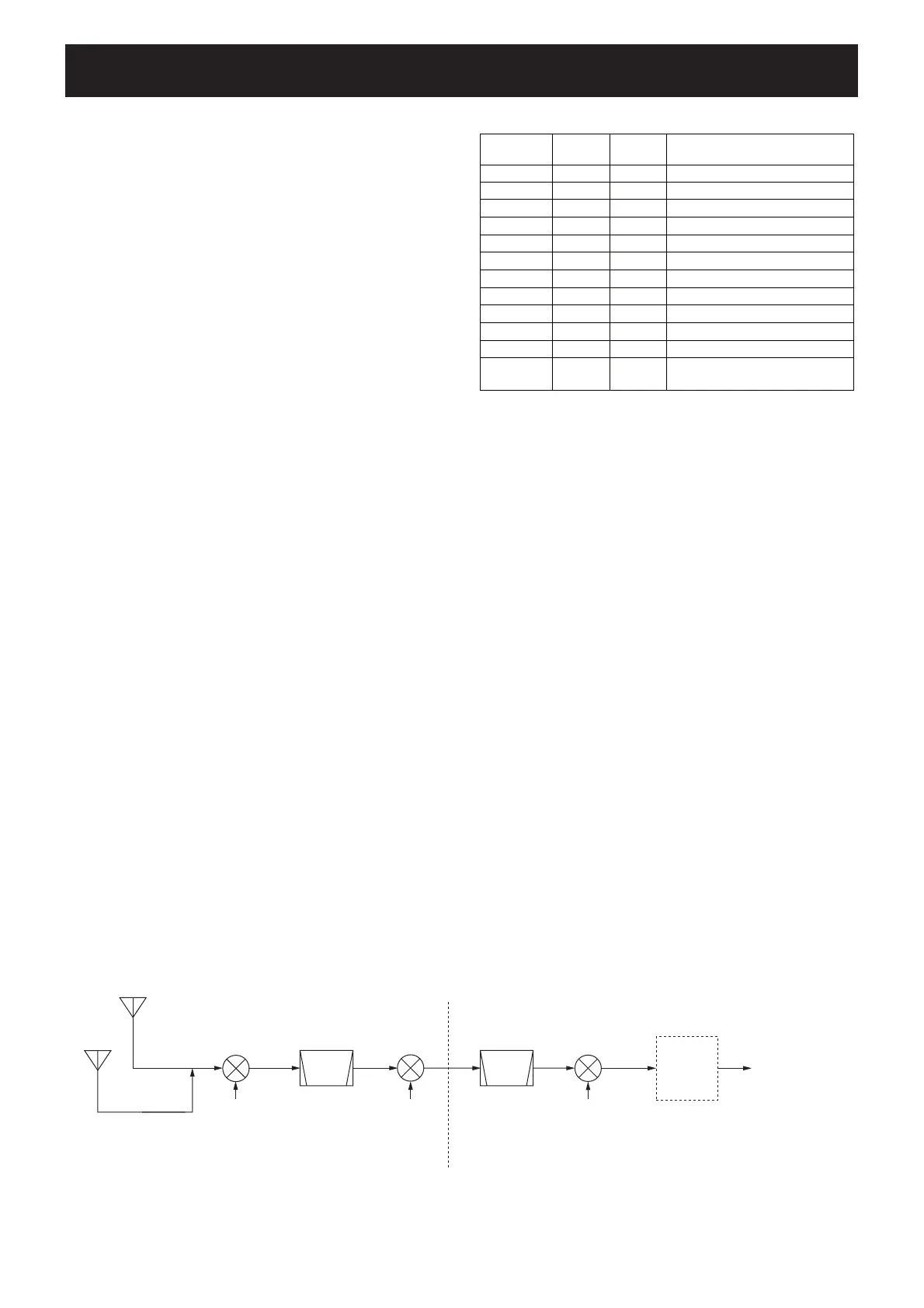
s2ECEIVERCONSTRUCTION
to squelch gate
(IC1160)
36 kHz
DSP
UNIT
0.03–60.0 MHz
ANT1 or ANT2
ANT
144 MHz
108–174 MHz
1st LO
2nd LO
64.0 MHz
Crystal
filter
Crystal
filter
FI231a/b
1st mixer
Q211, Q212
2nd mixer
D261
3rd LO
491 kHz
3rd mixer
IC280
64.455 MHz
FI272
455 kHz
2&UNIT -!).UNIT
s
SE
ER
&REQUENCy #ONTROL )NPUT
&ILTERCOMPONENT
RANGE SIGNAL DIODE
0.03–1.6 MHz
B0 D3
L11, L12, R11–R13, C12–C14, C17
1.6–2 MHz B1 D21 L21–L23, C21–C25
2–4 MHz B2 D31 L31–L33, C31–C35
4–8 MHz B3 D41 L41–L43, C41–C45
8–11 MHz B4 D51 L51–L53, C51–C55
11–15 MHz B5 D61 L61–L63, C61–C65
15–22 MHz B6 D71 L71–L73, C71–C75
22–30 MHz B7 D81 L81–L84, C81–C85
30–50 MHz B8W D101 L101–L103, C101–C105
50–54 MHz B8 D91 L91–L96, C90–C100
54–60 MHz B8W D101 L101–L103, C101–C105
108–174 MHz
B9R
None
D501, L501, L502
(via C500)
 Loading...