3 - 7
• FREQUENCY SYNTHESIZER CIRCUITS
FIL
LOOP
BUFF
PLL
IC
D/A
FIL
LOOPPLL
IC
BUFF
BPF
CERAMIC
DDS
FIL
LOOP
SPLIT
BPF
XTAL
D505
BPF
BPF
BPF
BUFF
BPF
BPF
MUTE
DDS
DDS LPF
BPF
MUTE
BUFF
AMP
AMP
AMP
AMP
AMP
AMP
AMP
BPF
CERAMIC
AMP LPFAMPLPFAMP
LPF
AMP D/A
BUFF BPF
2nd RX LO signal
2nd TX LO signal
64.0 MHz
DSP system clock signal
3rd TX LO signal
X2 BPF
64.491 MHz
84.455-
109.454999MHz
72.455-
84.454999MHz
64.485-
72.454999MHz
109.455-
124.455MHz
64.0MHz
PLL UNIT
64.485-
72.454999MHz
64.485-124.455 MHz
64.485-124.455 MHz
109.455-
124.455MHz
84.455-
109.454999MHz
72.455-
84.454999MHz
1st RX LO signals
1st RX/TX LO signals
D361
D362
Q361
I
C320
Q301
Q271
Q251
Q221
Q201
IC381
Q151
IC101
FI101
Q152
Q403
IC403
Q451
SUB LOOP VCO
Q452
R459-462
Q402
I
C402
FI401
R401-424
R701-720
I
C681
Q571
Q551
Q521
Q501
Q601
IC620
D661
D662
Q661
Q701
I
C701 Q702
L821,822
FI831
Q831
Q71
491 kHz
Q87
Q61 L61,62
Q801
BUFF
L53,C55–57
LPF
32MHz
32MHz
32MHz
32MHz
32MHz
32MHz
REFERENCE FREQUENCY
CILLATOR CIRCUIT
SUB LOOP
MAIN LOOP
2nd TX LO CIRCUIT
VCO-A
VCO-B
2nd RX LO CIRCUIT
DSP CLOCK CIRCUIT
Q51
X51
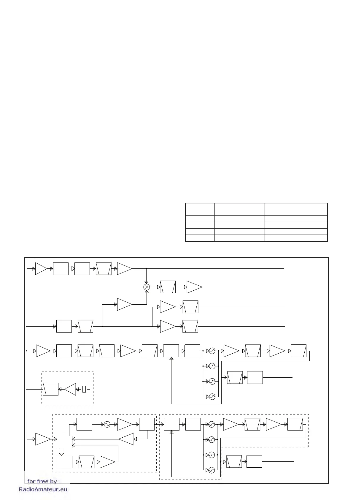
1ST RX (Sub readout) LO CIRCUITS (MAIN LOOP)
The applied PLL reference frequency signal is used for the
phase comparison of oscillating signal from the VCO-B
(Q501, 521, 551, 571). The resulting signal of phase
comparison is converted into the lock voltage which controls
the oscillation frequency of VCO-B (Q501, 521, 551, 571),
by being passed through the passive loop fi lter.
The output signals of the VCO-B (Q501, 521, 551, 571) are
buffer-amplifi ed by Q601, fi ltered by the BPF, and amplifi ed
by IC620, then fi ltered by the LPF for harmonic removal. The
fi ltered VCO output signals are passed through the BPF and
LO mute switch (Q661, D661, 662), then applied to the RF
UNIT as the 1st RX LO (for Sub readout) signals.
A portion of VCO output signals from the LPF are fed back
to the PLL (IC681) for the phase-locked loop.
VCOs (VCO-B)
Q501, Q521, Q551 and Q571 compose four oscillators,
and each VCO generates the 1st RX LO signals. These
VCO employ high "Q" components as resonator (L502, 522,
552, 572) for high C/N characteristic and wide oscillation
frequency range.
The table below shows the oscillation frequency range of
VCO-B and the RX frequency range.
Composed
by
RX Frequency range
Oscillation frequency range
(1st LO)
Q571 0.03–7.999999 MHz 64.485–72.454999 MHz
Q551 8–19.999999 MHz 72.455–84.454999 MHz
Q521 20–44.999999 MHz 84.455–109.454999 MHz
Q501 45–60 MHz 109.455–124.455 MHz
1ST RX (Sub readout) LO CIRCUITS (SUB LOOP)
The 32 MHz reference signal from the reference frequency
oscillator circuit is amplified to the C-MOS level by Q403,
and applied to the DDS (IC403) as the reference clock
signal.
The DDS (IC403) generates the DDS reference frequency
signal by using the reference clock signal. The DDS
reference frequency signal is converted its waveform by
the D/A converter (R401–424), fi ltered by FI401 to remove
unwanted components, and amplified to C-MOS level by
IC402, then applied to the phase comparator of DDS (IC403).
The applied DDS reference frequency signal is used for the
phase comparison of oscillating signal from the SUB LOOP
VCO (Q451). The resulting signal of phase comparison is
converted into the lock voltage which controls the oscillation
frequency of SUB LOOP VCO (Q451), by being passed
through the passive loop fi lter.
The output signal of SUB LOOP VCO (Q451) is amplifi ed by
the buffer (Q452), and applied to the PLL IC (IC681) as the
PLL reference frequency signal.
A portion of sub loop VCO (Q451) is applied to the phase
comparator of DDS (IC403) via the splitter (R459–461) and
AMP (Q402), for the phase-locked loop.
for
free
by
RadioAmateur.eu
 Loading...


