4 - 1
SECTION 4
ADJUSTMENT PROCEDURE
EQUIPMENT GRADE AND RANGE EQUIPMENT GRADE AND RANGE
Short plug
Modifi ed 3.5 mm (1/8’’) monoral plug
(See the illust on the page 4-17)
Audio generator
(AG)
Frequency range : 300–3000 Hz
Output level : 1–500 mV
RF voltmeter
(50
Ω
terminated)
Measuring range : 20–200 mV
Frequency range : 0.1–50 MHz
AC Millivoltmeter Measuring range : 10 mV to 10 V
RF power meter
(50
Ω
terminated)
Measuring range : 5–120 W
Frequency range : 0.1–50 MHz
SWR : Less than 1.2 : 1
Digital multimeter
Measuring range : 0–10 V (Voltage)
1–30 A (Current)
Input impedance : More than 50 k
Ω
Frequency counter
Frequency range : 0.1–100 MHz
Frequency accuracy : ±1 ppm or better
Input level : Less than 1 mW
External speaker
Input impedance : 8
Ω
Capacity : More than 2 W
Standard signal
generator (SSG)
Frequency range : 0.1–100 MHz
Output level : 0.1 mV to 32 mV
(–127 to –17 dBm)
Spectrum Analyzer
Frequency range : At least 90 MHz
Bandwidth : 100 kHz
Dummy Loads
Impedance : 50
Ω
/120 W
and
100
Ω
/120 W
¤ REQUIRED EQUIPMENTS
4-1 PREPARATION
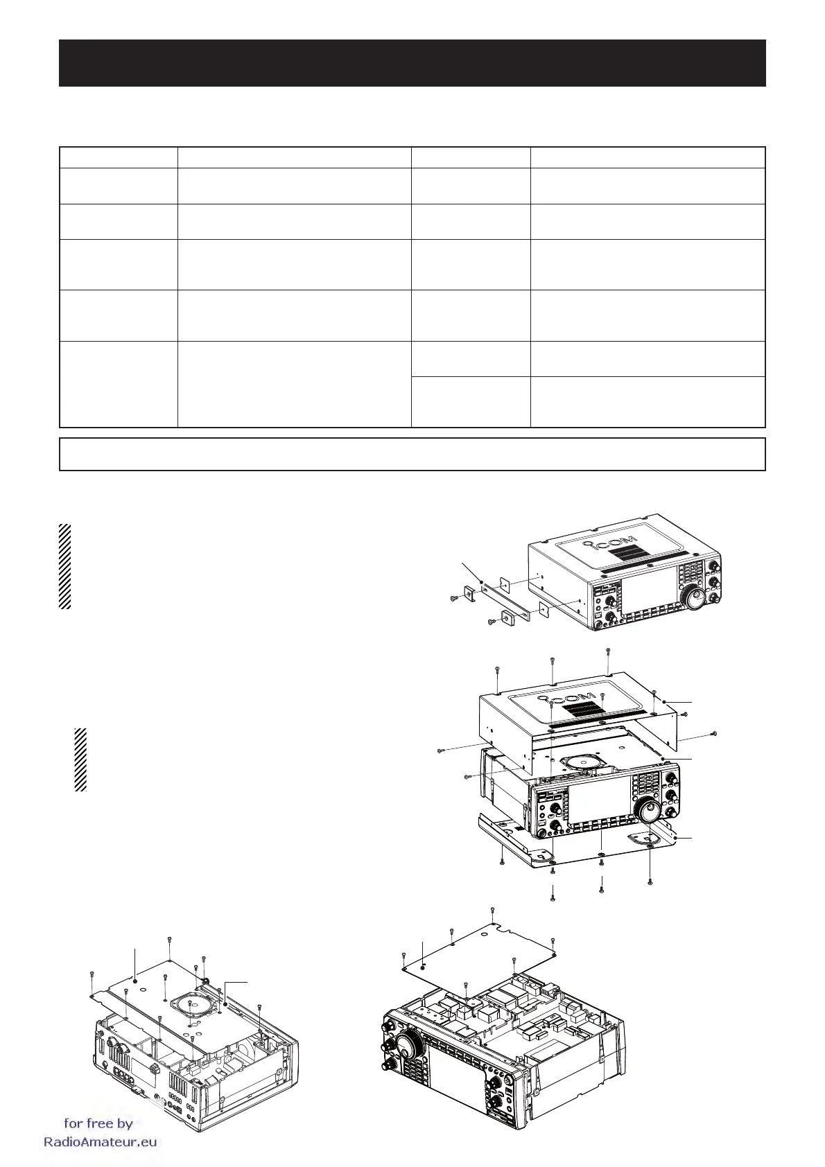
¤ REMOVING COVERS
Some adjustments require removal the covers to expose PCB.
CAUTION: Turn the power OFF and disconnect the
DC power cable from the transceiver before per-
forming any work on the transceiver. Otherwise,
there is danger of electric shock and/or equipment
damage.
q Remove the two screws from the carrying handle
and remove the handle from the transceiver.
w Remove the 6 screws from the top of the trans-
ceiver and the 4 screws from the sides, then lift up
the top cover.
e Turn the transceiver upside-down.
CAUTION: NEVER HOLD THE MAIN DIAL OR
ANY OTHER KNOBS when the transceiver is
being turned upside down. This may damage the
transceiver.
r Remove 6 screws from the bottom, then lift up the
bottom cover.
t Remove the 11 screws, and disconnect the speaker
cable, then remove the top shielding plate. <fig.1>
y Remove the 6 screws, then remove the bottom
shielding plate. <fig.2>
Top shielding plate
Bottom shielding plate
Speaker cable
Carrying handle
Top cover
Bottom cover
PA shielding
plate
<fig.1>
<fig.2>
CAUTION!:
SAVE the originally programmed contents
(Memory channel contents, set mode settings, etc.) into the USB-Memory
before starting adjustment. When all adjustments are completed, these contents in the transceiver will be cleared.
for
free
by
RadioAmateur.eu
 Loading...


