3 - 1
• RF CIRCUITS
SECTION 3
CIRCUIT DESCRIPTION
TUNER_
NETWORK
RL101
1.6-
LP F
0.03-
1.599999 MHz
TX circuits
LPF
PRE
AMP
Q4201/Q4202
PRE
AMP
Q4203
59.999999 MHz
8-
7.999999 MHz
ATT ATT
D131
CP3
CP4
CURRENT
DETECT
ANT1
J5 J6
ANT
2
TUNER
UNIT
CTRL UNIT
RF UNIT
To the 1st RX
IF circuits
B0
D801D802
RX ANT
6 dB12 dB
D201
PREAMP
BOARD
IN
OUT
D8 1
RL105
RL104
RL103
TX circuits
RL105
RL104
RL101
RL102
RL103
BPF BOARD
BPFs
(B1-B5)
RX FILTER CIRCUITS
BPFs
(B5-B10,
B10W)
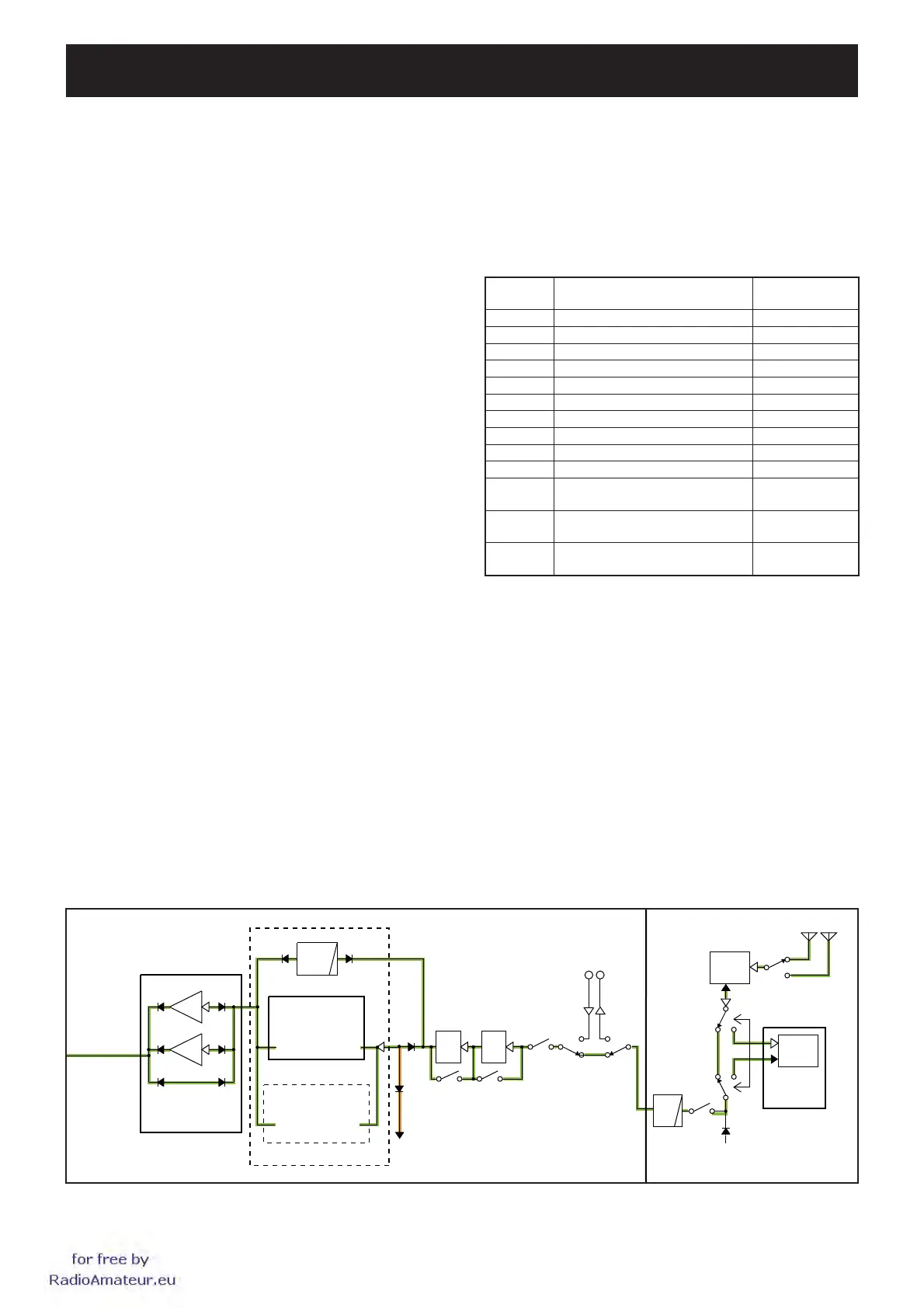
3-1 RECEIVER CIRCUITS
ANTENNA SWITCHING CIRCUIT AND ANTENNA
MATCHING CIRCUITS (CTRL AND TUNER UNITS)
RX signals from the antenna connector; [ANT1] (J5) or
[ANT2] (J6) are passed through the antenna switch (RL101)
and current detector (D81), and applied to the RF UNIT
via the tuner switches (RL104 and RL105), RX line switch
(RL103) and LPF.
If the automatic antenna tuning function is activated, the RX
signals from the current detection circuit (D81, 301, 302)
are applied to the antenna tuning network on the TUNER
UNIT to match the transceiver to the connected antenna
automatically.
The RX signals from the TUNER UNIT are applied to the RF
UNIT via the RX line switch (RL103) and LPF.
ATTENUATOR CIRCUITS (RF UNIT)
The RX signals from the CTRL UNIT are passed through
the RECEIVE ANTENNA IN/OUT CONNECTOR switches
(RL104, 105) and RX line cut switch (RL101), then passed
through or bypassed the attenuator circuits, according to the
setting.
The combination of attenuator (or bypass) that the RX
signals are passed through determines the entire attenuation
level; 0 dB, 6 dB, 12 dB or 18 dB.
The RX signals which are passed though or bypassed the
attenuator circuits are applied to the BPF circuits.
BPF CIRCUITS (RF UNIT AND BPF BOARD)
The RX signals from the attenuator circuits are passed
through an LPF or one of BPFs correspond to the operating
frequency, to remove unwanted out-of-band signals.
The table below shows filter which the RX signals are
passed in each frequency range.
Name of
BPF
Frequency range Located on
B0 0.03–1.599999 MHz RF UNIT
B1 1.6–1.999999 MHz BPF BOARD
B2 2.0–2.999999 MHz BPF BOARD
B3 3.0–3.999999 MHz BPF BOARD
B4 4.0–5.999999 MHz BPF BOARD
B5 6.0–7.999999 MHz BPF BOARD
B6 8–10.999999 MHz RF UNIT
B7 11–14.999999 MHz RF UNIT
B8 15–21.999999 MHz RF UNIT
B9 22–29.999999 MHz RF UNIT
B10
(for RX)
50–54 MHz RF UNIT
B10W
30–49.999999 MHz
54.000001–59.999999 MHz
RF UNIT
B10TX
(for TX)
50–54 MHz RF UNIT
The fi ltered RX signals are applied to the PREAMP BOARD.
PREAMPLIFIERS (PREAMP BOARD)
The RX signals from the BPF circuits are applied to or
bypassed the preamplifi er.
When the PREAMP FUNCTION is activated, the RX signals
are amplified by one of preamplifiers (Q4201, Q4202 or
Q4203).
The amplifi ed or bypassed RX signals are applied to the RF
UNIT again.
for
free
by
RadioAmateur.eu
 Loading...


