4 - 1
SECTION 4
CIRCUIT DESCRIPTION
4-1 RECEIVER CIRCUITS
4-1-1 ANTENNA SWITCHING CIRCUIT
The antenna switching circuit functions as a low-pass filter
while receiving and a resonator circuit while transmitting.
This circuit does not allow transmit signals to enter the
receiver circuits.
Received signals enter the antenna connector (CHASSIS;
J1) and pass through the low-pass filter (L1–L3, C2–C5,
C175, C176). The filtered signals are passed through the
1⁄4
λ type antenna switching circuit (D5, D6, L6, L7) and
then applied to the RF circuit.
4-1-2 RF CIRCUIT
The RF circuit amplifies signals within the range of fre-
quency coverage and filters out-of-band signals.
The signals from the antenna switching circuit pass through
the bandpass filter (D4, D8, L8, L9). The filtered signals are
amplified at the RF amplifier (Q2) and then passed through
the another bandpass filter (D9, D10, L11) to suppress
unwanted signals. The filtered signals are applied to the 1st
mixer circuit.
D4, D8–D10 employ varactor diodes, that are controlled by
the CPU via the D/A converter (IC8), to track the bandpass
filter. These varactor diodes tune the center frequency of an
RF passband for wide bandwidth receiving and good image
response rejection.
4-1-3 1ST MIXER AND 1ST IF CIRCUITS
The 1st mixer circuit converts the received signal into fixed
frequency of the 1st IF signal with the PLL output fre-
quency. By changing the PLL frequency, only the desired
frequency passes through a crystal filter at the next stage
of the 1st mixer.
The RF signals from the bandpass filter are mixed with
the 1st LO signals, where come from the RX VCO circuit
via the attenuator (R26–R28), at the 1st mixer circuit (Q3)
to produce a 46.35 MHz 1st IF signal. The 1st IF signal is
passed through a monolithic filter (FI1) in order to obtain
selection capability and to pass only the desired signal.
The filtered signal is applied to the 2nd IF circuit after being
amplified at the 1st IF amplifier (Q4).
4-1-4 2ND IF AND DEMODULATOR CIRCUITS
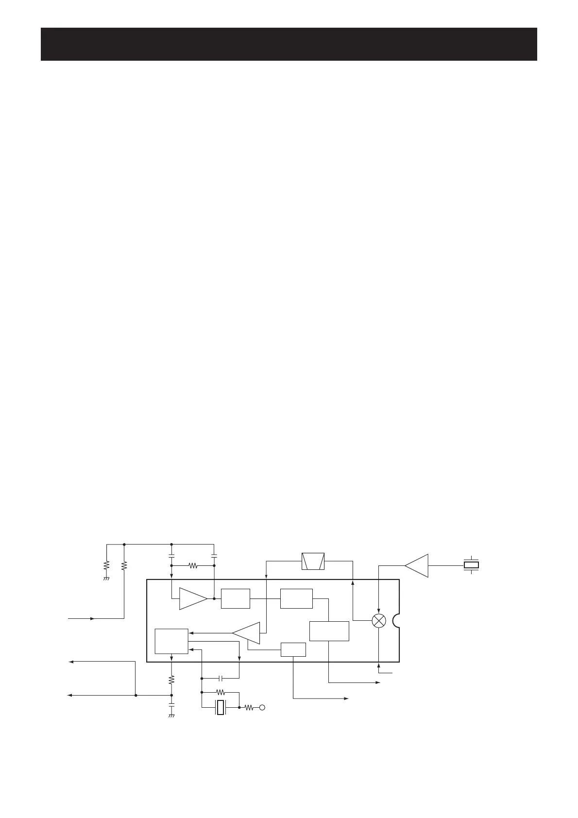
The 2nd mixer circuit converts the 1st IF signal into a 2nd
IF signal. The double-conversion superheterodyne system
(which convert receive signals twice) improves the image
rejection ratio and obtains stable receiver gain.
The 1st IF signal from the IF amplifier (Q4) is applied to
the 2nd mixer section of the FM IF IC (IC1, pin 16), and
is mixed with the 2nd LO signal to be converted into a
450 kHz 2nd IF signal.
The FM IF IC (IC1) contains the 2nd mixer, 2nd local oscil-
lator, limiter amplifier, quadrature detector, active filter and
noise amplifier circuits. A 2nd LO signal (45.9 MHz) is pro-
duced at the PLL circuit by tripling it’s reference frequency
(15.3 MHz).
The 2nd IF signal from the 2nd mixer (IC1, pin 3) passes
through the ceramic filter (FI2) to remove unwanted het-
erodyned frequencies. It is then amplified at the limiter
amplifier section (IC1, pin 5) and applied to the quadrature
detector section (IC1, pins 10, 11) to demodulate the 2nd
IF signal into AF signals.
The demodulated AF signals are output from pin 9 (IC1) as
“DET” signal, and are then applied to the AF circuit.
2ND IF AND DEMODULATOR CIRCUITS
Mixer
16
Limiter
AMP
2nd IF filter
450 kHz
X2
15.3 MHz
45.9 MHz
IC1 TA31136FN
12
1st IF signal from the IF amplifier (Q4)
"RSSI" signal to the CPU (IC13, pin 63)
11109
87
5
AF signal "DET"
to the AF circuit
"SQLC" signal from the
D/A converter IC
(IC8, pin 2)
To D/A converter IC
(IC8, pin 1)
R5V
X1
2
Active
filter
Noise
detector
FM
detector
13
"NOIS" signal to the CPU (IC13, pin 53)
RSSI
Noise
AMP
Noise
comparator
×3
Q19
FI2
3
 Loading...