5 - 6
5-3 TRANSMIT ADJUSTMENT
1) Select an adjustment item using cursor or [
↑
] / [
↓
] keys of the PC’s keyboard.
2) Set or modify the adjustment value as specifi ed using [
←
] / [
→
] keys of the PC’s keyboard, then push the [ENTER] key.
ADJUSTMENT ADJUSTMENT CONDITION OPERATION
ADJUSTMENT
ITEM
VALUE
TRANSMIT
OUTPUT
POWER
-Preparation-
1
<For IC-F14S/F15S/F16S only>
Clone the "ADJ CH TXPWR.icf" into the transceiver.
–
• Connect an RF Power Meter to the
antenna connector. – –
-Adjustment-
Hi
2 • CH. (16CH/2CH) : CH.3/CH.1
• Transmitting
1) Adjust the transmit output power
using [
←
] / [
→
] keys on the PC’s
keyboard.
2) Push the [ENTER] key to store the
adjust value.
[Power (Hi)] 5.0 W
L2 3 • CH. (16CH/2CH) : CH.4/CH.2
• Transmitting
[Power (L2)]
2.0 W
L1 4 • CH. (16CH/2CH) : CH.5/CH.3
• Transmitting
[Power (L1)]
1.0 W
DEVIATION
-Preparation-
1
<For IC-F14S/F15S/F16S only>
Clone the "ADJ CH AudioMOD.icf" into the transceiver.
• Connect a Modulation Analyzer
to the antenna connector
through an Attenuator.
• Set the Modulation Analyzer as;
HPF : OFF
LPF : 20 kHz
De-emphasis : OFF
Detector : (P-P)/2
– –
2• Connect an Audio Generator
to the MIC line through the JIG
cable.
• Set the Audio Generator as;
Modulation : 1 kHz
Level : 40 mV rms
Wave form : Sine wave
– –
-Adjustment-
WIDE
3 • CH. (16CH/2CH) : CH.5/CH.2
• Transmitting
1) Adjust the deviation using [
←
] / [
→
]
keys on the PC’s keyboard.
2) Push the [ENTER] key to store the
adjust value.
[MOD Ratio]
±4.05–4.15
kHz
MIDDLE* 4 • CH. (16CH/2CH) : CH.6/CH.1
• Transmitting [MOD Ratio]
±3.15–3.25
kHz
NARROW 5 • CH. (16CH/2CH) : CH.7
• Transmitting [MOD N]
±2.05–2.15
kHz
MODULATION
BALANCE
-Preparation-
1
<For IC-F14S/F15S/F16S only>
Clone the "ADJ CH ToneMOD.icf" into the transceiver.
• Connect a Modulation Analyzer
to the antenna connector
through an attenuator.
• Set the Modulation Analyzer as;
HPF : OFF
LPF : 20 kHz
De-emphasis : OFF
Detector : (P-P)/2
––
• Connect an Oscilloscope to
the Detect terminal of the
Modulation Analyzer.
– ––
-Adjustment-
NARROW
2 • CH. (16CH/2CH) : CH.8/CH.1
• Transmitting
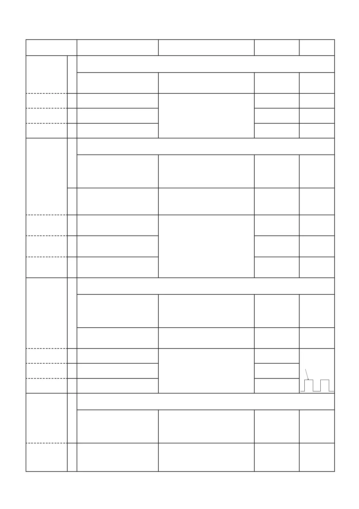
1) Adjust the waveform using [
←
] / [
→
]
keys on the PC’s keyboard.
2) Push the [ENTER] key to store the
adjust value.
[BAL N]
Square
waveform
MIDDLE* 3 • CH. (16CH/2CH) : CH.8/CH.1
• Transmitting
[BAL Ratio]
WIDE 4 • CH. (16CH/2CH) : CH.9/CH.2
• Transmitting
[BAL Ratio]
CTCSS/DTCS
DEVIATION
-Preparation-
1
<For IC-F14S/F15S/F16S only>
Clone the "ADJ CH ToneMOD.icf" into the transceiver.
• Connect a Modulation Analyzer
to the antenna connector
through an attenuator.
• Set the Modulation Analyzer as;
HPF : OFF
LPF : 20 kHz
De-emphasis : OFF
Detector : (P-P)/2
––
-Adjustment- 2 • CH. (16CH/2CH) :
CH.10/CH.3
• Transmitting
1) Adjust the deviation using [
←
] / [
→
]
keys on the PC’s keyboard.
2) Push the [ENTER] key to store the
adjust value.
[CTCSS/DTCS]
±0.66–0.70
kHz
Flat
*: F15/S only
 Loading...