4 - 5
Scrambler/
De-scrambler
TX/RX
HPF
Pre-
emphasis
Limiter Splatter VR2
Expander
VR4
RXA2
SMF
De-
emphasis
Com-
pressor
VR1
(HPF)
RX
LPF
VR3
(HPF)
7 MOD
18
19
20 SIGNAL
3TXIN
23RXIN
21SDEC
10
14MDIR
9
MTDT
MTCK
13MSCK
11MDIO
12MRDF
MSK
Modulator
MSK
Demodulator
MSK
BPF
Control
Register
TXA1
RXA1
• DIGITAL MODE CIRCUIT
BPF
From FM IF IC
(IC12)
To AF amplifier circuit
From
MIC amplifier
(FRONT UNIT; IC15)
To FM/PM SW
(IC43)
AMP
AMP
AMP
Q3
IC42
RECEIVED SIGNAL
FI3
IC15
IC16
IC41
IC18
IC18 IC13
IC44
IC42
IC2
A/D
LINER
CODEC
IC
LINER
CODEC
IC
BASE
BAND
IC
DIG/ANA
SW
DSP
IC
MIC SW
LPF
TRANSMIT SIGNAL
4-5 OTHER CIRCUITS
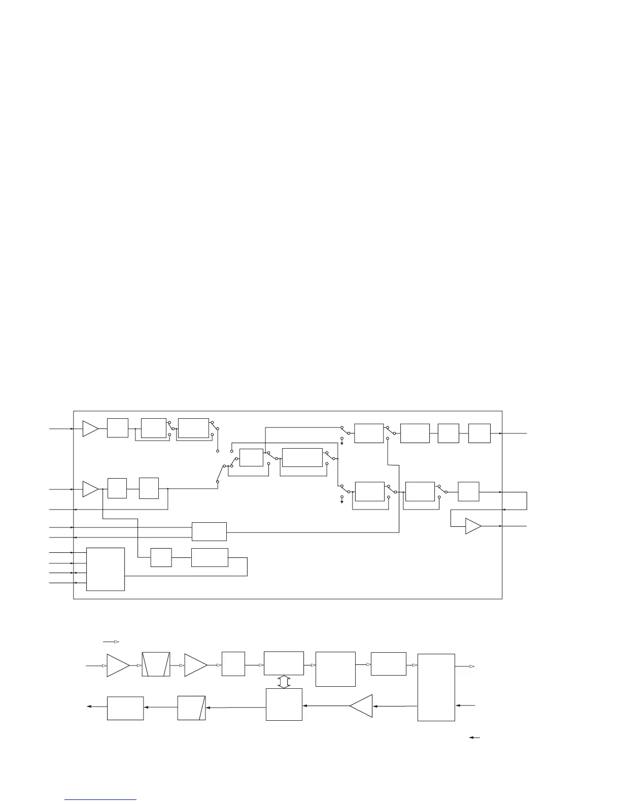
4-5-1 COMPANDER CIRCUIT (MAIN UNIT)
IC-F2700/2800 series have compander circuit which can
improve S/N ratio and become wide dynamic range. The
circuit is composed in the base band IC (IC2).
(1) WHILE RECEIVING
The demodulated AF signals from the FM IF IC (IC12, pin
9) are applied to the amplifi er section in base band IC (IC2,
pin 23), and then pass through the low-pass and high-pass
filter section to suppress unwanted signals. The filtered
signals pass through (or bypass) scrambler section, and are
then applied to the expander circuit to expand AF signals.
The output signals from the base band IC (IC2, pin20)
is applied to the AF amplifier circuit after amplified at the
amplifi er section.
(2) WHILE TRANSMITTING
The audio signals from the microphone are applied to the
base band IC (IC2, pin 3) via microphone amplifi er (FRONT
UNIT; IC5). The signals are amplifi ed at the amplifi er section,
and are then applied to the compressor circuit to compress
the audio signals. The signals pass through (or bypass)
scrambler section, and are then applied to the limiter section
after being passed through the high-pass fi lter.
The filtered signals pass through the splatter filter section,
and are then applied to the modulation circuit (D12) via the
FM/PM switch (IC43, pins12–14) and D/A converter (IC8,
pins 2, 3).
4-5-2 DIGITAL MODE CIRCUIT (IC-F2721D/F2821D only)
(1) WHILE RECEIVING
A portion of the 2nd IF signal from the limiter amplifi er sec-
tion in the FM IF IC (IC12) output from pin 11 and is ap-
plied to the IF amplifi er (Q3). The amplifi ed signal is passed
through a ceramic bandpass fi lter (FI3) to suppress hetero-
dyne noise, and amplified again at the digital IF amplifier
(IC15, pins, 1, 4). The amplifi ed 2nd IF signal is applied to
the A/D converter (IC16) to be converted into digital IF sig-
nal, then applied to the DSP IC (IC41). The DSP IC converts
the digital IF signal into the digital audio signal.
The digital audio signal from DSP IC are converted into ana-
log audio signals at the LINER CODEC IC (IC18) and output
from pin 16.
The audio signals are applied to the base band IC (IC2,
pin 23) after being pass through the DIG/ANA switch (IC42,
pins 1, 15).
(2) WHILE TRANSMITTING
The microphone signal from the base band IC (IC2, pin 7)
are amplifi ed at the MOD amplifi er (IC44, pins 3, 4) and are
then applied to the LINER CODEC IC (IC18, pin 2) to con-
vert into the digital audio signal.
The digital audio signal is processed by DSP IC (IC41), and
applied to the LINER CODEC IC (IC18) again.
The signal from the LINER CODEC IC (IC18, pin 15) is
passed through the low-pass fi lter (IC13, pins 1, 3, 6, 7) and
then applied to the PM/FM switch (IC43, pins 12–14) after
pass through the microphone switch (IC42 pins 13, 14).
• BASE BAND IC DIAGRAM (IC2: AK2346-E2)
 Loading...