28
4
CONNECTION AND MAINTENANCE
n Optional UT-109 or UT-110 installation (Continued)
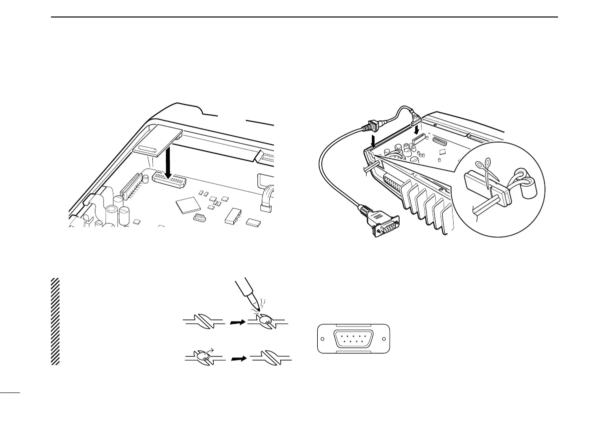
r Install the unit as shown in the diagram below.
t Replace the bottom cover and screws, then re-connect the
DC power cable.
nOptional OPC-617 installation
Install the OPC-617 as shown below.
OPC-617
Cut off the bushing as in the
illustration, when you install
the optional OPC-617.
q
Dimmer cont. IN
w AF OUT
e Det. AF OUT
r Mod. IN
t PTT control IN or
y Horn drive cont. OUT
u AF GND
i Det. AF GND
o Mod. GND
OPTIONAL CABLE PIN ASSIGNMENT
t r e w q
o i u y
FTSW control IN
NOTE: When uninstalling
the unit
Be sure to re-solder the
disconnected points and
un-solder the connected
points as above when you
remove the unit. Otherwise
no TX modulation or AF
output is available.

 Loading...