5 - 1
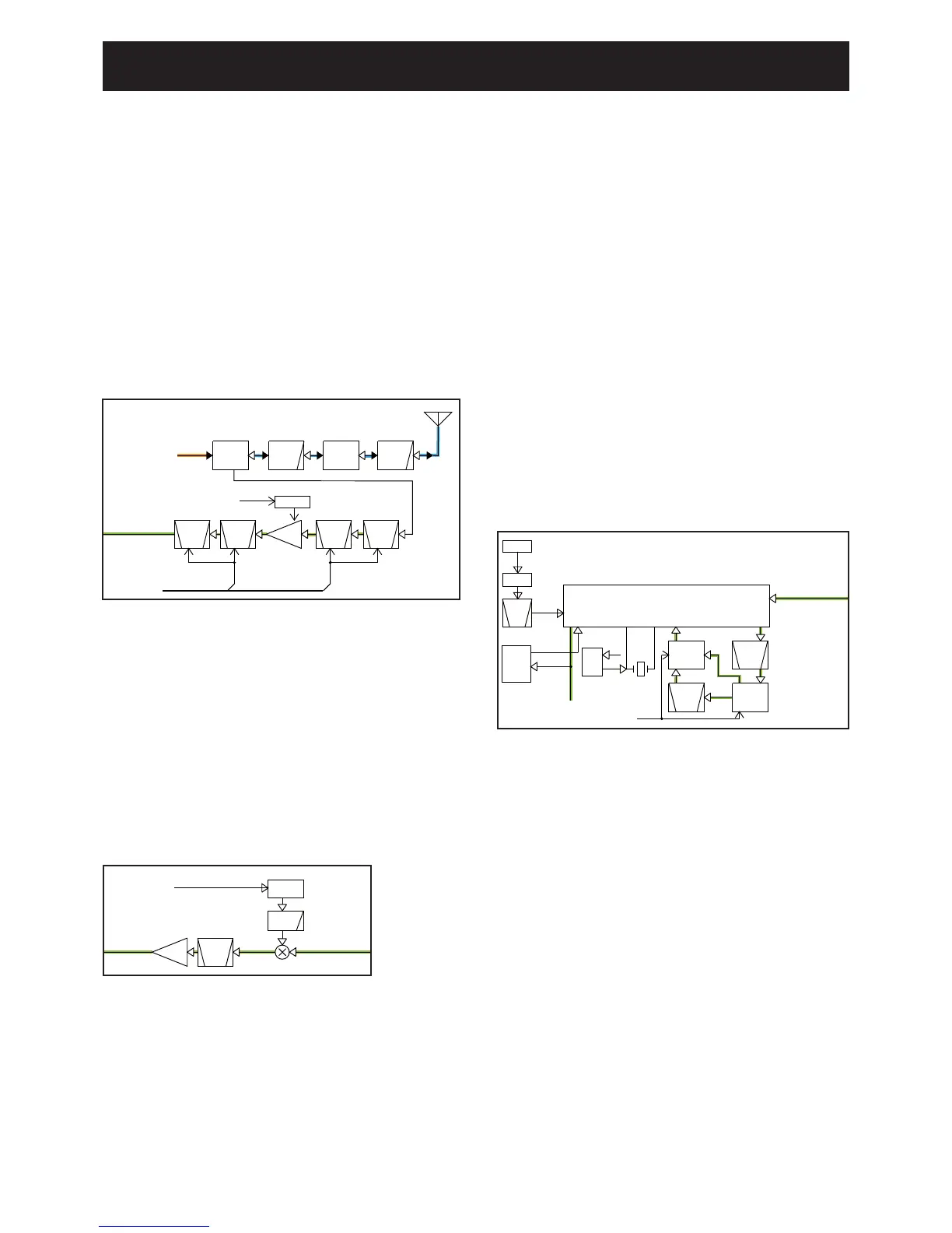
1ST IF CIRCUITS
The RX signals from the BPF are mixed with the 1st LO
signals to be converted into the 46.35 MHz 1st IF signal.
The 1st LO signals are generated by the RX VCO (Q14,
D33, D34, L26, L39, etc.), and passed through the LO SW
(D15) and attenuator, then applied to the 1st mixer (Q3)
The converted 1st IF signal is filtered by the crystal filter (FI1)
and amplified by the 1st IF AMP (Q4), then applied to the IF
IC (IC1).
5-1 RECEIVER CIRCUITS
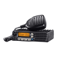
RF CIRCUITS
RF signals from the antenna are passed through the LPF (as
the harmonic filter for transmitting) and antenna SW, then
applied to the RX BPF circuit.
The applied RX signals are passed through the 2-staged
tuned BPF (D4, D8) to remove unwanted out-of-band
signals, and amplified by the low-noise RF AMP (Q2), then
applied to the 1st mixer (Q3) via another 2-staged tuned
BPF (D9, 10).
Total of 4 stage BPF are tuned to the RX frequency by the
tuning voltage “T1” and “T2” from the D/A converter (IC20),
to obtain required IMD characteristic.
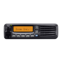
2ND IF AND DEMODULATOR CIRCUITS
The amplified 1st IF signal is mixed with the 2nd LO signal
at the internal 2nd IF mixer of the IF IC (IC1), to obtain the
450 kHz 2nd IF signal.
The 15.3 MHz signal generated by the reference oscillator
(X2) is passed through the filter AMP (Q34, L33, 35, C305–
308) to extract the 45.9 MHz 3rd harmonic component. The
45.9 MHz signal is then applied to pin 2 of IF IC (IC1) as
the 2nd LO signal.
The converted 2nd IF signal is output from pin 3 of IF IC
(IC1), and filtered by the ceramic filters (FI2 and FI6 for
Narrow mode; FI2 only for Wide mode) to remove unwanted
out-of-band signals, then applied to the internal frequency-
demodulator of IF IC (IC1) from pin 5.
The demodulator is a quadrature type which uses X1 as the
phase shifter.
The frequency-demodulated AF signals are output from pin 9
to AF circuits.
• RF CIRCUITS
• 2ND IF AND DEMODULATORCIRCUITS
• 1ST IF CIRCUITS
SECTION 5
 Loading...