3
1
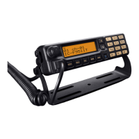
PANEL DESCRIPTION
n Function display
01 c h-0 1
Ic-F9511T
uqw erty i
!0
o
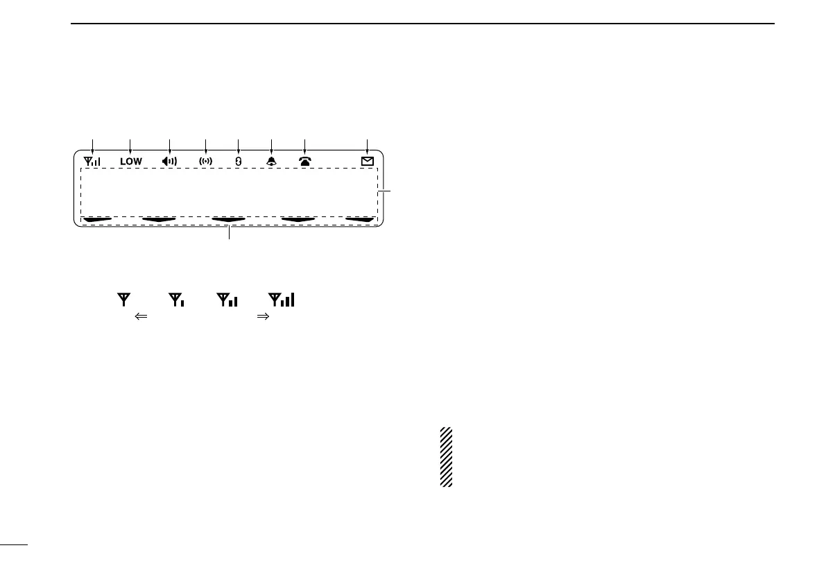
q RECEIVED SIGNAL STRENGTH INDICATOR
Indicates relative signal strength level.
Weak Receive Signal level Strong
w LOW POWER INDICATOR
Appears when low output power is selected.
•Whenhighoutputpowerisselected,noindicatorappears.
e AUDIBLE INDICATOR
Appears when the channel is in the ‘audible’ (unmute)
condition.
r COMPANDER INDICATOR
Appears when the compander function
* is activated.
* Analog mode operation only
t SCRAMBLER INDICATOR
Appears when the voice scrambler or encryption function
is activated.
y BELL INDICATOR
Appears/blinks when a matched signal is received, de-
pending on the pre-programming.
u TELEPHONE INDICATOR
Appears when a phone call* is received.
* P25 operation only
i SHORT MESSAGE INDICATOR
Appears when an Status message or Short message is
received.
o ALPHANUMERIC DISPLAY
Displays an operating channel number, channel name,
Set mode contents, DTMF code, etc.
!0 ACTIVATED KEY INDICATOR
Appears above the key assigned as [Scan Add/Del (Tag)]
key when that key has been activated.
See the operating guide for details of Analog, MDC and
P25 Trunking/Conventional system operations. Consult
your Icom dealer or system operator for details concern-
ing your transceiver’s programming.
 Loading...