2
5
INSTALLATION AND CONNECTIONS
■ Unpacking
After unpacking, immediately report any damage to the
delivering carrier or dealer. Keep the shipping cartons.
For a description and a diagram of accessory equip-
ment included with the IC-FR3000/FR4000 series, see
‘Supplied accessories’ on p. iii of this manual.
■ Selecting a location
Select a location for the repeater that allows adequate
air circulation, free from extreme heat, cold, or vibra-
tions, and away from TV sets, TV antenna elements,
radios and other electromagnetic sources.
■ Antenna connection
For radio communications, the antenna is of critical im-
portance, along with output power and sensitivity. Se-
lect antenna(s), such as a well-matched 50 Ω antenna,
and feedline. 1.5:1 or better of Voltage Standing Wave
Ratio (VSWR) is recommended for desired band. Of
course, the transmission line should be a coaxial
cable.
CAUTION: Protect repeater from lightning by using
a lightning arrestor.
NOTE: There are many publications covering
proper antennas and their installation. Check with
your local dealer for more information and recom-
mendations.
■ Duplexer
A duplexer is separately required when only one an-
tenna is used for both transmitting and receiving. Se-
lect a duplexer according to the transmitting and re-
ceiving frequencies. Ask your Dealer for details.
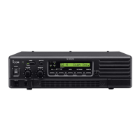
■ Grounding
To prevent electrical shock, television interference
(TVI), broadcast interference (BCI) and other prob-
lems, ground the transceiver through the [GND] termi-
nal on the rear panel.
For best results, connect a heavy gauge wire or strap
to a long earth-sunk copper rod. Make the distance be-
tween the [GND] terminal and ground as short as pos-
sible.
RR
WARNING: NEVER connect the [GND] termi-
nal to a gas or electric pipe, since the connection
could cause an explosion or electric shock.
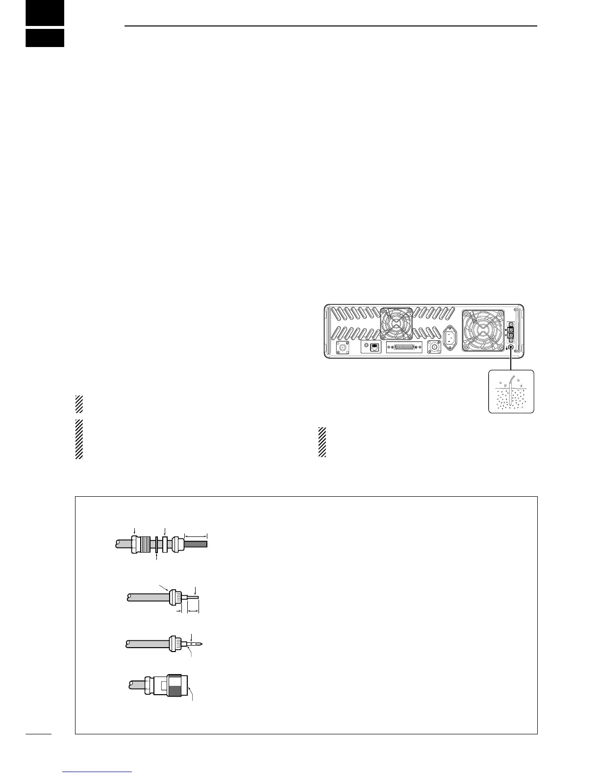
Slide the nut, flat washer, rubber gasket and clamp over the coaxial
cable, then cut the end of the cable evenly.
Strip the cable and fold the braid back over the clamp.
Soft solder the center conductor. Install the center conductor pin and
solder it.
Carefully slide the plug body into place aligning the center conductor
pin on the cable. Tighten the nut onto the plug body.
q
w
e
r
15 mm
3 mm
6 mm
No space
Solder hole
Be sure the center conductor is
the same height as the plug body.
Clamp
Center
conductor
Washer
Nut Rubber gasket
 Loading...