5 - 1
SECTION 5 ADJUSTMENT PROCEDURE
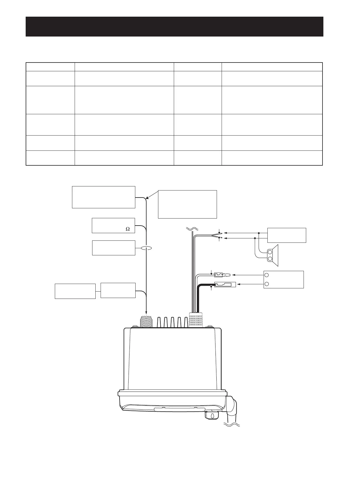
¤ REQUIRED TEST EQUIPMENTS
EQUIPMENT GRADE AND RANGE EQUIPMENT GRADE AND RANGE
DC power supply
Output voltage : 13.8 V DC
Current capacity : More than 10 A
DC voltmeter Input impedance : 50 k
Ω
/V DC or more
RF power meter
(terminated type)
Measuring range : 0.1–30 W
Frequency range : 100–300 MHz
Impedance : 50
Ω
SWR : Less than 1.2 : 1
Standard signal
generator (SSG)
Frequency range : 0.1–300 MHz
Output level : 0.1
µ
V to 32 mV
(–127 to –17 dBm)
Frequency counter
Frequency range : 0.1–300 MHz
Frequency accuracy : ±1 ppm or better
Sensitivity : 100 mV or better
AC millivoltmeter Measuring range : 10 mV to 10 V
FM deviation meter
Frequency range : 30–300 MHz
Measuring range : 0 to ±10 kHz
External speaker
Input impedance : 4
Ω
Capacity : More than 5 W
Audio generator
Frequency range : 300–3000 Hz
Output level : 1–500 mV
Attenuator
Power attenuation : 40 dB
Capacity : More than 30 W
5-1 PREPARATION
¤ CONNECTIONS
FM
IC-M304
deviation meter
to the antenna connector
Attenuator
40 dB
Power supply
13.8 V/10 A
SINAD meter
Blue: Speaker (+)
Speaker (4 Ω)
Gray: Speaker (−)
RF power meter
0.1–30 W/50
Frequency
counter
Standard signal generator
0.1 µV to 32 mV
(–127 dBm to –17 dBm)
CAUTION!
DO NOT transmit while
the SSG is connected to
the antenna connector
Red: Positive (+)
Black: Negative (−)
+
−
+
−

 Loading...