5 - 2
5-2 FREQUENCY ADJUSTMENT
ADJUSTMENT
ADJUSTMENT
CONDITION
OPERATION VALUE
LOCK
VOLTAGE
(Verify)
1 • Channel : CH16 (156.800 MHz)
• Receiving
Connect a DC voltmeter to the check point ‘LV.’ 1.3–2.3 V
(Verify)
2 • Channel : CH16 (156.800 MHz)
• Output power : Low
• Connect a power meter to the ant-
enna connector.
• Transmitting
1.4–2.4 V
(Verify)
REFERENCE
FREQUENCY
1 • Channel : CH16 (156.800 MHz)
• Output power : Low
• Connect a power meter to the ant-
enna connector.
• Transmitting
1) Loosely couple a frequency counter to the ant-
enna connector.
2) Adjust C257 (REF).
156.800 MHz
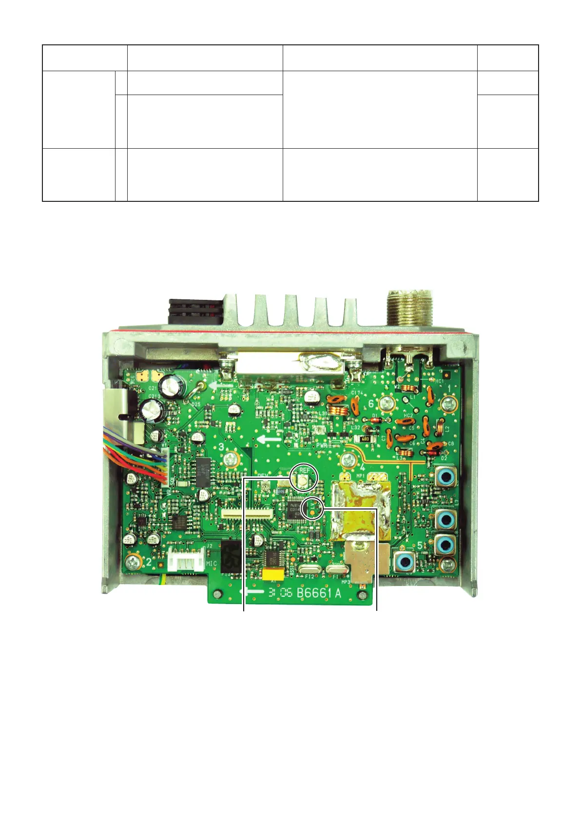
• ADJUST&CHECK POINTS LOCATION (FREQUENCY)
“LV”
LOCK VOLTAGE
CHECK POINT
C57 (REF)
RECEIVE SENSITIVITY
ADJUSTMENT POINT

 Loading...