!1 SQUELCH LEVEL INDICATOR
Shows the squelch level.
!2 VOLUME LEVEL INDICATOR
➥ Shows the volume level.
➥ The bars appear in ascending order repeatedly while
the volume loud function is activated. (p. 12)
➥
Blinks while the volume mute function is activated. (p. 12)
!3 VOLUME LEVEL ADJUSTING INDICATOR (p. 11)
➥ Blinks while adjusting the volume level.
➥ This indicator and the volume level indicator appear
alternately while the volume level is turned up by the
noise detection function. (p. 20)
!4 SQUELCH LEVEL ADJUSTING INDICATOR (p. 12)
Blinks while adjusting the squelch level.
!5 CHANNEL NUMBER READOUT
➥ Indicates the selected operating channel number.
➥ In the set mode, indicates the selected condition or
value.
(p. 17)
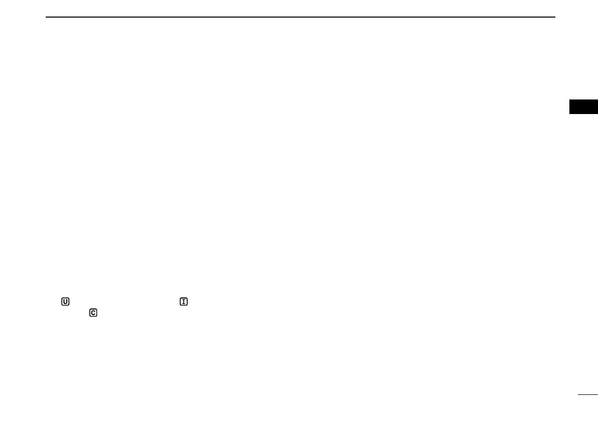
!6 CHANNEL GROUP INDICATOR (p. 9)
“
” appears when U.S.A.*
1
; “ ” appears when Interna-
tional; “
” appears when Canadian*
2
channel group is
selected.
*
1
U.K. and China versions only.
*
2
China version only.
!7 ATIS INDICATOR (p. 9)
“ATIS” appears when the channel group, which ATIS func-
tion is activated, is selected. (Available with German and
Holland versions only.)
!8 LOW POWER INDICATOR (p. 10)
➥ “LOW” appears when low power is selected.
➥ “LOW” blinks when switching forced low power mode
because of a high temperature error or low voltage.
7
3
PANEL DESCRIPTION
1
2
3
4
5
6
7
8
9
10
11
12
13
14
15
16

 Loading...