CIRCUIT DESCRIPTION
4-1 RECEIVE CIRCUITS
RF CIRCUIT (MAIN UNIT)
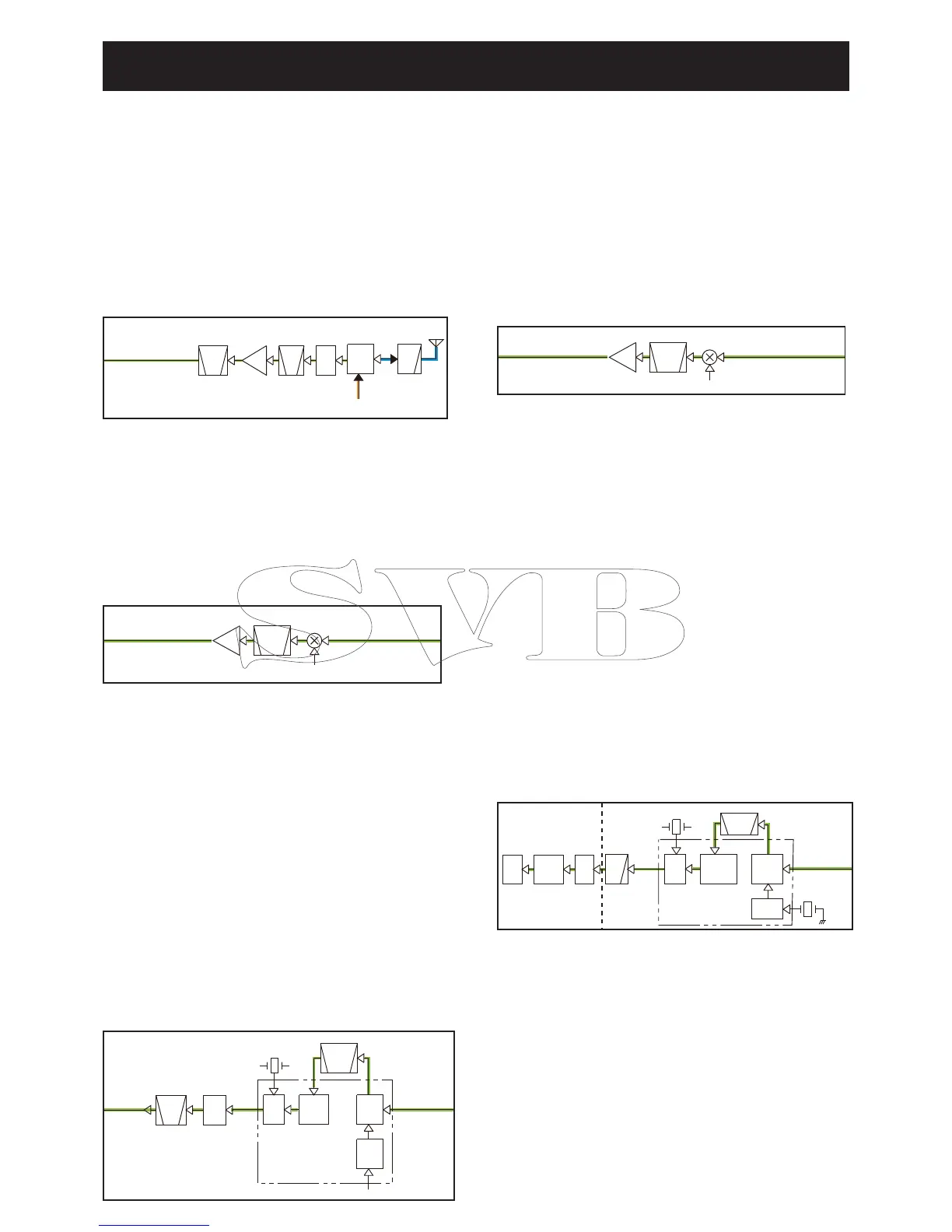
The RX signal from the antenna is passed through the LPF
(L21, L22, and C114–C116), ANT SW (D16), attenuator (D19,
R96) and BPF (L201, C201 and C202), and then applied to
the RF AMP (Q201).
The amplifi ed signal is divided and applied to the 1st IF cir-
cuits for MAIN CH or CH70, through another BPF (FI201: for
MAIN CH; L301–L303 and C302–C308: for CH70).
1ST IF CIRCUIT FOR MAIN CHANNELS (MAIN UNIT)
The RX signal from the RF circuits is applied to the 1st IF
mixer (Q202), and mixed with the 1st LO signal from the VCO
(Q3, Q4 and D1–D3), resulting in a 21.7 MHz 1st IF signal.
The 1st IF signal is fi ltered by the 1st IF fi lter (FI202 and
FI203), and then applied to the 1st IF AMP (Q203). The am-
plifi ed signal is applied to the 2nd IF circuits.
2ND IF CIRCUIT FOR MAIN CHANNELS (MAIN UNIT)
The 1st IF signal from the 1st IF circuits is applied to the IF IC
(IC201, pin 16). The IF IC contains the 2nd IF mixer, 2nd IF
AMP, detector, and so on, in its package.
The 1st IF signal is mixed with the 21.25 MHz 2nd LO signal
from the reference frequency oscillator (TCXO: X101), result-
ing in a 450 kHz 2nd IF signal. The 2nd IF signal is passed
through the 2nd IF fi lter (FI204) to remove sideband noise.
The fi ltered signal is amplifi ed by the 2nd IF AMP, and de-
modulated by the quadrature detector with discriminator
(X201).
The demodulated AF signal is applied to the RX AF circuits,
through the AF SW (IC504B, pins 4, 3).
1ST IF CIRCUIT FOR CH70 (MAIN UNIT)
The RX signal from the RF circuits is applied to the 1st IF
mixer (Q302), and mixed with the 125.649 MHz 1st LO signal
which is generated by the TCXO (X401) and tripled by the
BPF (L402, L403 and C412–C416), resulting in a 30.875 MHz
1st IF signal.
The 1st IF signal is fi ltered by the 1st IF fi lters (FI302 and
FI303), and then applied to the 1st IF AMP (Q303). The am-
plifi ed signal is applied to the 2nd IF circuits.
2ND IF CIRCUIT FOR CH70 (MAIN and LOGIC UNITS)
The 1st IF signal from the 1st IF circuits is applied to the IF IC
(IC301, pin 16). The IF IC contains the 2nd IF mixer, 2nd IF
AMP, detector, and so on, in its package.
The 1st IF signal is mixed with the 30.425 MHz 2nd LO signal
which is generated by 2nd LO oscillator (X302), resulting in
a 450 kHz 2nd IF signal. The 2nd IF signal is passed through
the 2nd IF fi lter (FI304) to remove sideband noise. The fi ltered
signal is amplifi ed by the 2nd IF AMP, and demodulated by
the quadrature detector with discriminator (X301).
The demodulated AF (FSK; Frequency Shift Keying) signal is
applied to the DSC decoder (LOGIC UNIT: IC11, pin 2) which
converts the sub audible tone signal into serial data, through
the LPF (Q702) and DSC SW (LOGIC UNIT: IC3, pins 7, 1).
The serial data is applied to the CPU (LOGIC UNIT: IC1,
pin 103) to control the transceiver (emergency alarm, DSC
indication and so on.).
• RF CIRCUIT
• 1ST IF CIRCUIT (For main channels)
• 2ND IF CIRCUIT (For main channels)
• 2ND IF CIRCUIT (For CH70)
BPF
RF
AMP
ANT
LPF
BPF
ANT
SW
ATT
Q201FI201
D14,D16
Transmit circuits
To the 1st IF circuits
D19
D18
IF
AMP
1st LO signal
BP F
XTAL
21.7MHz
FI202,FI203
Q 203
From the RF circuits
(MAIN CH)
To the 2nd IF circuits
(MAIN CH)
Q202
1st IF mixer
1st LO signal
IF
AMP
BPF
XTAL
To the 2nd IF circuits
(CH70)
From the 1st IF circuits
(CH70)
FI302,FI303
Q302
30.875MHz
Q303
1st IF mixer
BPF
CERAMIC
BPF
X201
MAINDET
To the RX
AF circuits
2ND
MIX
2ND IF
AMP
FM
DET
2ND LO
BUFF
IC201
FI204
From the
1st IF circuits
(MAIN CH)
21.25 MHz
AF
IC506B/C
SW
IC504B
BPF
CERAMIC
X301
X302
CH70DET
MAIN
UNIT
LOGIC UNIT
From the
1st IF circuits
(CH70)
DET MIX
2ND LO
2ND IF
IC301
BUFF
AMP
FM 2N D
FI304
30.425MHz
LPF
Q702
DSC
SW
IC3
DSC
DECODER
IC11
CPU
IC1
• 1ST IF CIRCUIT (For CH70)
 Loading...