4-3
4-2 TRANSMIT CIRCUITS
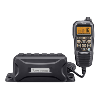
TX AF CIRCUIT (MAIN UNIT)
The AF signal from the COMMANDMICIV™ is passed
through the MIC mute SWs (IC502C, pins 9, 8 and IC502B,
pins 4, 3), and then applied to the MIC AMP (IC513D).
TX AF CIRCUIT (MAIN UNIT)
The amplifi ed AF signal is passed through the AF SW (IC901,
pins 6, 1) and applied to the noise canceller IC (IC902,
pin 36).
The processed AF signal is output from pin 26, and then
passed through the LPF (IC905, pins 1, 4) and AF SW
(IC904, pins 1, 6), and then applied to the D/A converter
(IC514, pins 13, 14) to be adjusted in level.
The level-adjusted AF signal is applied to the IDC AMP
(IC513B) which limits the amplitude of MIC signal to prevent
over deviation. The amplitude-limited signal is passed through
the LPF (IC513C), and then applied to the modulation circuits
on the VCO UNIT.
MODULATION CIRCUIT (VCO UNIT)
The MIC signal from the TX AF circuits is applied to the VCO
(Q3, Q4 and D1–D3). The modulation signal is applied to D2,
to obtain Frequency Modulation.
The modulated VCO output signal is passed through the buf-
fers (Q5 and Q7), and then applied to the TX AMP circuits as
a TX signal, through the LO SW (MAIN UNIT: D7).
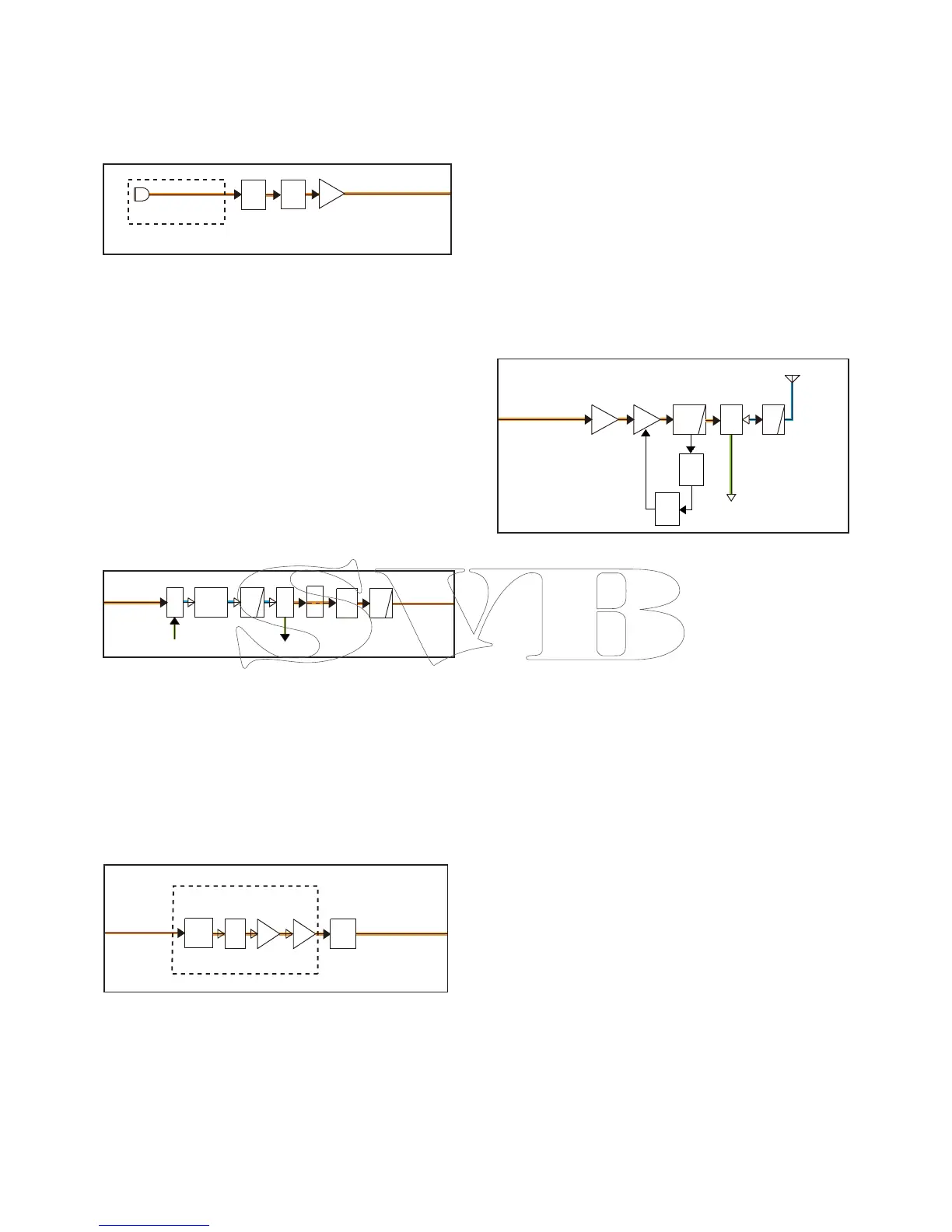
TX AMP CIRCUIT (MAIN UNIT)
The TX signal is amplifi ed by the YGR (Q13) and power AMP
(IC1), and then passed through the LPF (L20, C111 and
C112), TX output power detector (D12 and D13), ANT SW
(D14), and two LPF (L21, L22, and C114–C116), before be-
ing sent to the antenna.
APC CIRCUIT (MAIN UNIT)
The voltage produced at the LPF (L20, C111, and C112) is
rectifi ed by D12 and D13, and is used as the TX power sens-
ing voltage.
The voltage is applied to the APC AMP (IC2, pin 3), and the
output voltage controls the gate bias voltage of power AMP
(IC1) to keep the TX output power constant.
• TX AMP CIRCUIT
• MIC AMP CIRCUITS
• TX AF CIRCUIT
• MODULATION CIRCUIT
AF
MUTE
MIC
AMP
AF
MUTE
MAIN UNIT
IC513D
To the TX AF circuits
IC502B
IC502C
COMMANDMIC
BUFF
BUFF
LO
SW
VCO
From the
TX AF circuits
To the
TX AMP circuits
Q3,Q4
Q5
D7
D3
VCO UNIT
SHIFT
Q2
D1,D2
Q7
Q8
ANT
LPF
ANT
SW
YGR
AMP
PWR
AMP
LPF
From the modulation
circuits
Q13
D14,D16
RX circuits
IC1
APC
CTRL
PWR
DET
D12,
D13
IC2
LPF
LPF
From the
MIC AMP circuits
To the
modulation
circuits
IC514
D/A
IC513C
NOISE
CANCELLER
AF
SW
IC901
IC902
AF
SW
IC904IC905
IC513B
IDC
From the
demodulation
To the
RX AF circuits
 Loading...