July 2013
4-4
4-3
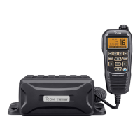
FREQUENCY SYNTHESIZER
• VCO (VCO UNIT)
The VCO (Q3, Q4, and D1–D3) generates both 1st LO signal
for MAIN channels and the TX signal.
The output of buffer (Q7) is used as the TX or RX LO signal.
While receiving, the LO signal is applied to the 1st IF mix-
er for MAIN channels (MAIN UNIT: Q202), through the LO
SW (MAIN UNIT: D8) and LPF (MAIN UNIT: L206, L207 and
C262).
While transmitting, the LO signal is applied to the TX AMP
circuits, through the LO SW (MAIN UNIT: D7).
• PLL (MAIN UNIT)
A portion of VCO output signal is passed through two buffers
(VCO UNIT: Q5 and Q6), and then fed back to the PLL IC
(IC101, pin 16).
The PLL IC (IC101) phase-compares the outputs of the refer-
ence frequency oscillator (TCXO; X101) and VCO, and the
phase-difference is output as the charge pump current.
The current is passed though the loop fi lter (R1–R3, C1–C3,
and C10) to be converted into the lock voltage, which controls
the oscillating frequency of VCO.
When the oscillation frequency drifts, its phase changes from
that of the reference frequency, causing a lock voltage change
to compensate for the drift in the VCO oscillating frequency.
• FREQUENCY SYNTHESIZER CIRCUIT
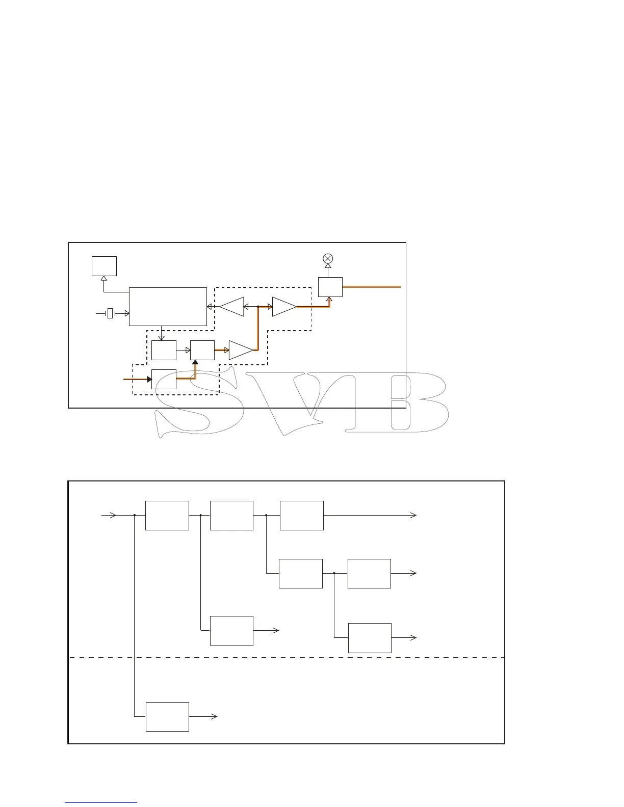
4-4 VOLTAGE BLOCK DIAGRAM
Voltage from the power supply is routed throughout the transceiver, through regulators and switches.
BUFFBUFF
X101
21.25MHz
BUFF
FILTER
LOOP
TX/RX
SW
IF IC
PLL
VCO
IC201
IC101
Q3,Q4
Q5
Q6
D7,D8
To the TX AMP circuits
D3
VCO UNIT
MAIN UNIT
SHIFT
Q2,Q8
D1,D2
MOD
From the TX AF circuits
Q7
Q202
1st mixer
(MAIN CH)
MAIN UNIT
LOGIC UNIT
PWR
CTRL
Q511,Q512
HV
Power
supply
+5 V
REG
IC512
5V
VCC
T5
CTRL
Q10,Q11
T5V
+3 V
REG
IC511
3V
R3
CTRL
Q12,Q23,Q24
R3V
Receive circuits
Receive
circuits
Transmit circuits
R8
REG
Q21,Q22
R8V
3.3 V
REG
IC4
L3V
CPU
+1.1 V
REG
IC903
Noise canceller
 Loading...