83
10
CONNECTIONS AND MAINTENANCE
r DC POWER CONNECTOR
Connects to a 13.8 V DC power source.
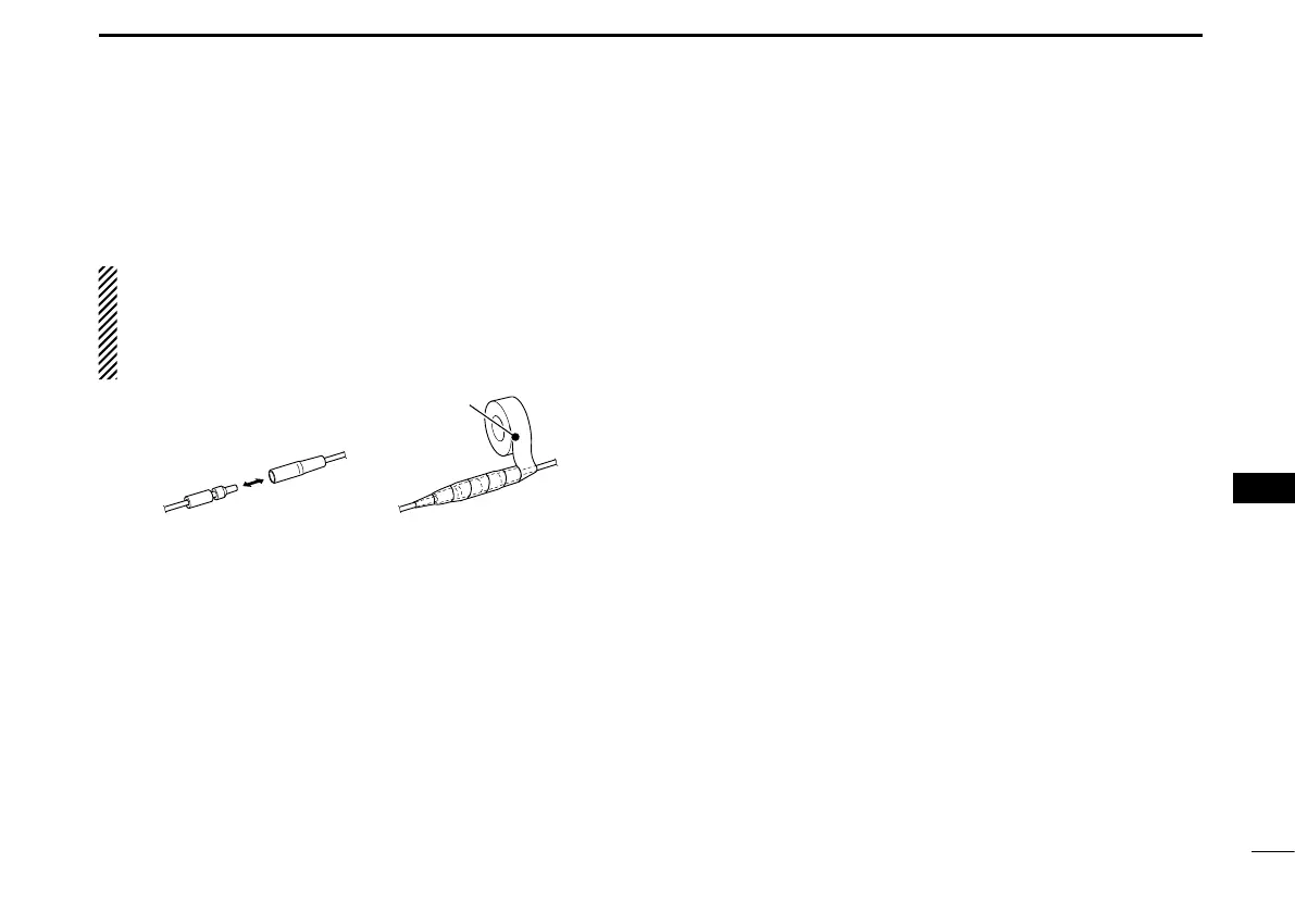
CAUTION: After connecting the DC power cable, NMEA
leads, external speaker leads, and PA speaker leads, cov-
er the connector and leads with an vulcanizing tape, as
shown below, to prevent water seeping into the connec-
tion.
t GROUND TERMINAL
Connects to a vessel ground to prevent electrical shocks
and interference from other equipment occurring.
Use a PH M3 × 6 screw (user supplied).
y COMMAND MICROPHONE JACK
Connects to the optional Command microphone. (p. 87)
Connect to the MA-500TR D
Connect the transceiver to the high-density D-Sub 15-pin
connector of the MA-500TR using the OPC-2014* cable. Af-
ter connecting, an Individual DSC call can be made to the
AIS target using the transponder without entering the target’s
MMSI code.
* The OPC-2014 is supplied with the MA-500TR
• Listener A (Data-H) lead (Yellow):
Connects to lead 3 of the OPC-2014.
• Listener B (Data-L) lead (Green):
Connects to lead 2 of the OPC-2014.
• Talker A (Data-H) lead (White):
Connects to lead 5 of the OPC-2014.
• Talker B (Data-L) lead (Brown):
Connects to lead 4 of the OPC-2014.
1
2
3
4
5
6
7
8
9
10
11
12
13
14
15
16
 Loading...