5 - 2
5-2 PLL ADJUSTMENTS
LOCK
VOLTAGE
REFERENCE
FREQUENCY
ADJUSTMENT
ADJUSTMENT ADJUSTMENT CONDITION
MEASUREMENT
VALUE
POINT
UNIT LOCATION UNIT ADJUST
1
2
3
4
1
• Operating channel : ch16
• Receiving
• Operating channel : ch116
• Receiving
• Operating channel : ch16
• Output power : Low
• Transmitting
• Operating channel : ch116
• Output power : Low
• Transmitting
• Operating channel : ch16
• Output power : Low
• Connect an RF power meter or a
50 Ω dummy load to the antenna
connector.
• Transmitting
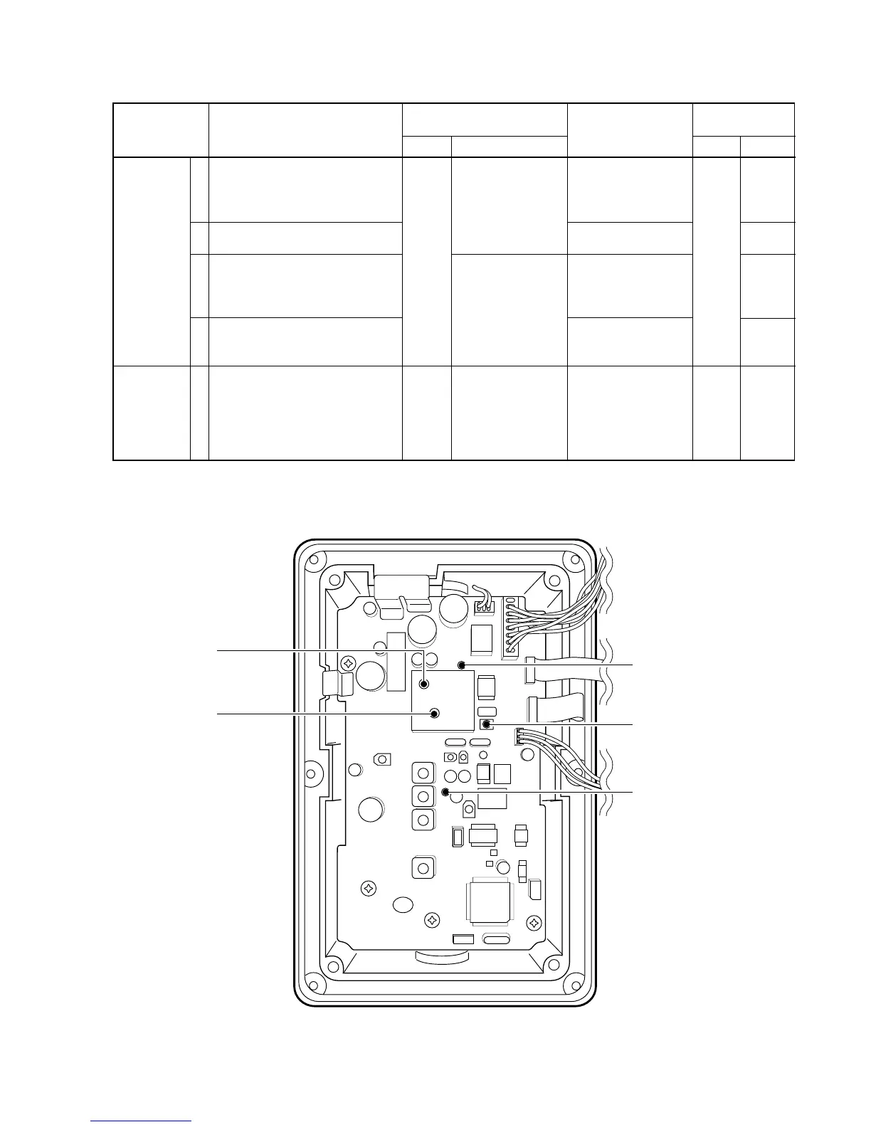
MAIN
Rear
Panel
Connect a digital
multi-meter or oscil-
loscope to check
point CP1.
Connect a digital
multi-meter or oscil-
loscope to check
point CP2.
Loosely couple the
frequency counter
to the antenna con-
nector.
3.5 V
4.5–6.0 V
2.5 V
2.5–3.5 V
156.8000 MHz
MAIN
MAIN
L13
Verify
L10
Verify
C70

 Loading...