5 - 4
*This output level of a standard signal generator (SSG) is indicated as SSG’s open circuit.
5-4 RECEIVER ADJUSTMENTS
SENSITIVITY
SQUELCH
ADJUSTMENT
ADJUSTMENT ADJUSTMENT CONDITION
MEASUREMENT
VALUE
POINT
UNIT LOCATION UNIT ADJUST
1
1
• Operating channel : ch16
• [SQUELCH] control:
Max. counterclockwise
• Set the internal speaker OFF in
the SET mode, and connect a
distortion meter with a 4 Ω load to
[EXT SP] receptacle.
• Connect an SSG to the antenna
connector and set as:
Frequency : 156.800 MHz
Level : 10 µV*
(–97 dBm)
Modulation : 1 kHz
Deviation : ±3.5 kHz
• Receiving
• Operating channel : ch16
• [SQUELCH] control:
Max. counterclockwise
• Connect an SSG to the antenna
connector and set as:
Frequency : 156.800 MHz
Level : 0.18 µV*
(–122 dBm)
Modulation : 1 kHz
Deviation : ±3.5 kHz
• Receiving
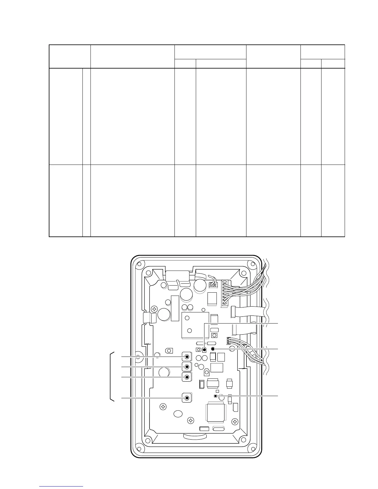
MAIN
MAIN
Connect a DC volt-
meter to check point
CP3.
Connect a DC volt-
meter to check point
CP5.
Maximum voltage
2 V
MAIN
MAIN
L1,
L2,
L3,
L4,
R33

 Loading...