SECTION 3 DISASSEMBLY INSTRUCTION
3 - 1
CAUTION: DISCONNECT the DC power cable from
the transceiver before performing any work on the trans-
ceiver. Otherwise, there is danger of electric shock and/or
equipment damage.
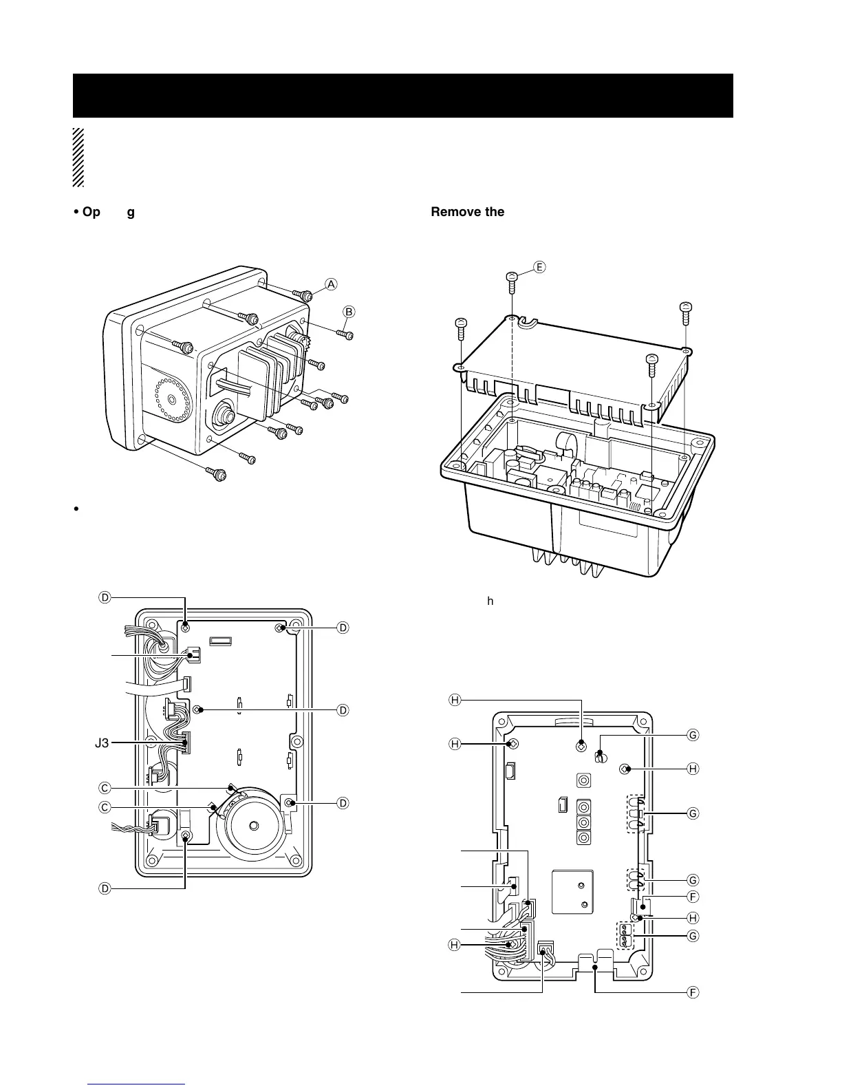
• Removing the LOGIC unit
q Unsolder 2 point C.
w Disconnect microphone connector from J1 and SQL/DIAL
connector from J3.
e Unscrew 5 screws D, and remove the LOGIC unit.
• Opening the transceiver case
q Unscrew 6 screws A, and remove the front unit.
w Unscrew 6 screws B, and remove the rear panel.
w Remove the 2 clips F.
e Disconnect microphone connector from J7 and CTRL
connector from J3 and EX-SP connector from J8 and
EX-GPS connector from J2.
r Unsolder 10 point G.
t Unscrew 5 screws H, and remove the MAIN unit.
• Remove the MAIN unit
q Unscrew 4 screws E from the shielding plate, then lift up
the shielding plate.

 Loading...