5 - 1
SECTION 5 ADJUSTMENT PROCEDURES
¤ REQUIRED TEST EQUIPMENTS
EQUIPMENT GRADE AND RANGE EQUIPMENT GRADE AND RANGE
Standard signal
generator (SSG)
Frequency range : 0.1–3300 MHz
Output level : 0.1 µV to 32 mV
(–127 to –17 dBm)
AC milliwattmeter Measuring range : 10 µW to 100 mW
Frequency counter
Frequency range : 0.1–30 MHz
Frequency accuracy : ±1 ppm or better
Sensitivity : 100 mV or better
External speaker
Input impedance : 8
Ω
Capacity : More than 5 W
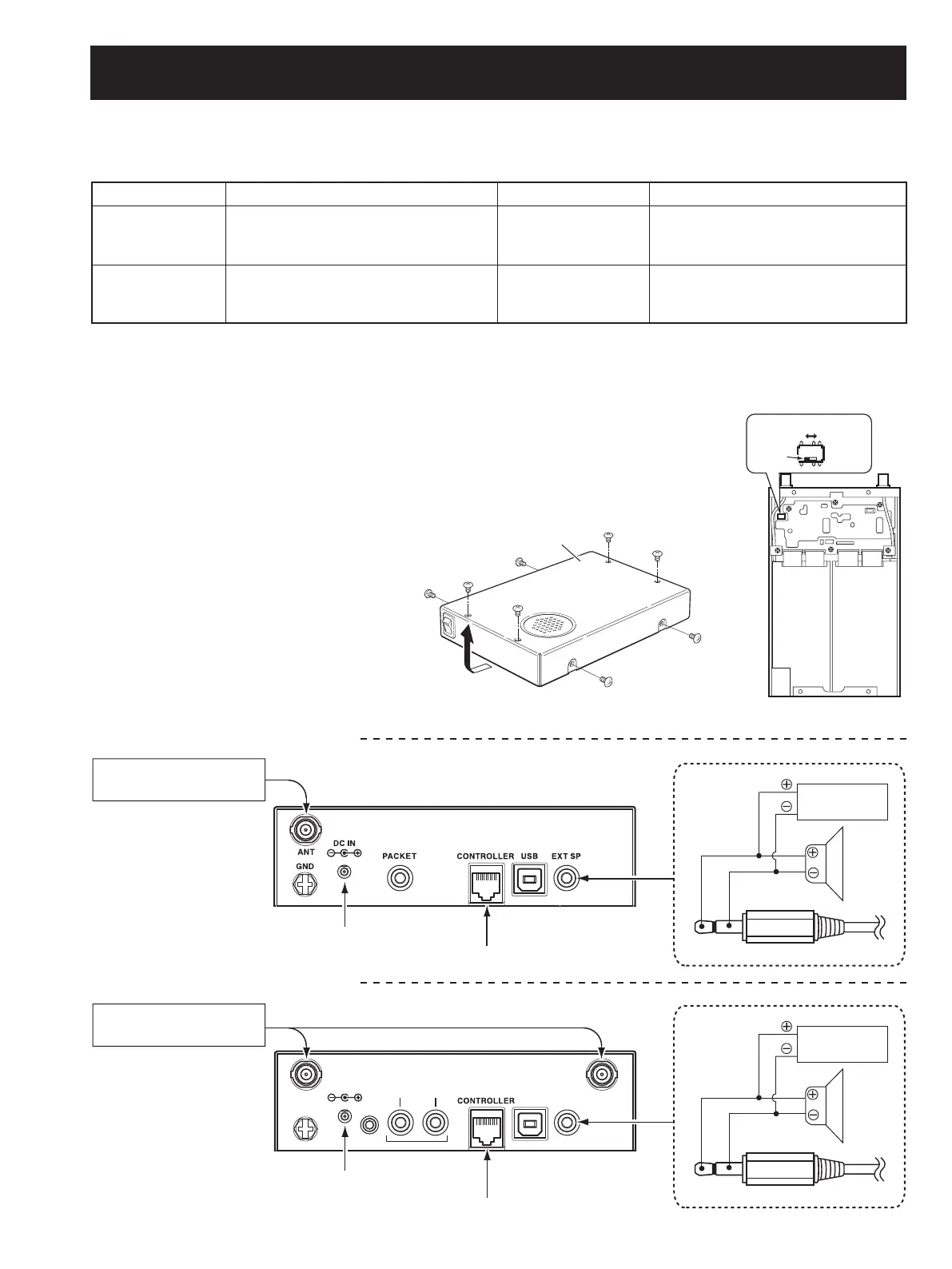
5-1 PREPARATION
When adjusting IC-PCR1500/PCR2500, controller for the R1500/R2500 and JIG cable (see the illust below) are required.
CAUTION!: BACK UP the originally programmed memory data in the receiver before starting the adjustment.
There is possiblity of losing original memory data when the adjustment is finished.
TOTHESUPPLIED!#ADAPTER
TOTHESUPPLIED!#ADAPTER
TOTHE)#2#/.42/,,%2
2EARPANEL
2EARPANEL
TOTHE)#2#/.42/,,%2
s*)'CABLE
!#
MILLIVOLTMETER
!&
'.$
3PEAKER
7
CONDUCTORDMM
v7
3TANDARDSIGNALGENERATOR
33'
3TANDARDSIGNALGENERATOR
33'
/PTIONALPRODUCTFOR;5+=
!4!$
4%+#!0
0348%"
3
5
4.! 4.!
.
)#$
$.'
4
%+#!0
s*)'CABLE
!#
MILLIVOLTMETER
!&
'.$
3PEAKER
7
CONDUCTORDMM
v7
• CONNECTION
Before starting adjustment:
• Remove the top cover and sheild cover on the MAIN-A UNIT. (Refer to the “SECTION 3” for details)
• Set the AF switch to “PHONES.” (Refer to the instruction manual for details)
<FOR IC-PCR1500 ADJUSTMENT>
<FOR IC-PCR2500 ADJUSTMENT>
2%
+
!
%
0
3
3%
.
/
(
0
HCT
IWS
4OPCOVER
 Loading...