5 - 3
ADJUSTMENT OPERATION VALUE
REFERENCE
FREQUENCY
[REF]
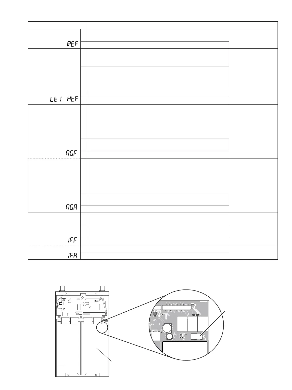
1 • Connect a frequency counter to the J5 connector on the MAIN-A
UNIT (see the illust below).
10.25000 MHz
2 • Push [TS•MODE]/[SET•SKIP] to store the set value.
BPF
[LT1]–[HTF]
1 • Preset the adjustment items as below before the “BPF“ adjustment.
[AGA] : “8A”
[IFA] : “25”
Automatic adjustment
2 • Connect an SSG to the antenna connector “ANT1” and set as;
Frequency : Specifi ed frequency*
Modulation : none
Level : Specifi ed level
†
3 • Push [TS•MODE]/[SET•SKIP] to store the adjustment value.
4 • Repeat 2–3 for each specifi ed frequency and level for [LT1] to [HTF].
AGC GAIN
(FM)
[AGF]
1 • Connect an SSG to the antenna connector and set as;
Frequency : Specifi ed frequency*
Mode : FM
Modulation : 1 kHz
Deviation : 3.5 kHz
Level : +34 dBµ (–73 dBm)
‡
50 mW
2 • Connect a speaker and milliwatt meter then set the audio output level
to 50 mW with [VOL].
3 • Push [SET•LOCK]/[MAIN•NB] to select next adjustment item.
(AM)
[AGA]
4 • Set the SSG as;
Frequency : Specifi ed frequency*
Mode : AM
Modulation : 1 kHz
Deviation : 70%
Level : +34 dBµ (–73 dBm)
‡
50 mW
5•
•
Set the audio output level to 50 mW with [DIAL].
Verify that the demodulated audio signals are not distorted badly.
6 • Push [TS•MODE]/[SET•SKIP] to store the adjustment value.
IF GAIN
(FM)
[IFF]
1 • Set the SSG as;
Level : OFF
50 mW
2 • Connect a speaker and milliwatt meter then set the audio output level
to 50 mW with [VOL].
3 • Push [SET•LOCK]/[MAIN•NB] to select next adjustment item.
(AM)
[IFA]
4 • Set the audio output level to 80 µW with [DIAL]. 80 µW
5 • Push [TS•MODE]/[SET•SKIP] to store the adjustment value.
5-2 MAIN-A UNIT ADJUSTMENT
*Displayed on the controller's display.
J5
2EMOVETHESHEILDCOVER
-!).!5.)4
‡
The output level of the standard signal generator (SSG) is indicated as the SSG's open circuit.
–
†
Refer to the “ADJUSTMENT ITEM LIST“ on page 5-7.
 Loading...