5 - 2
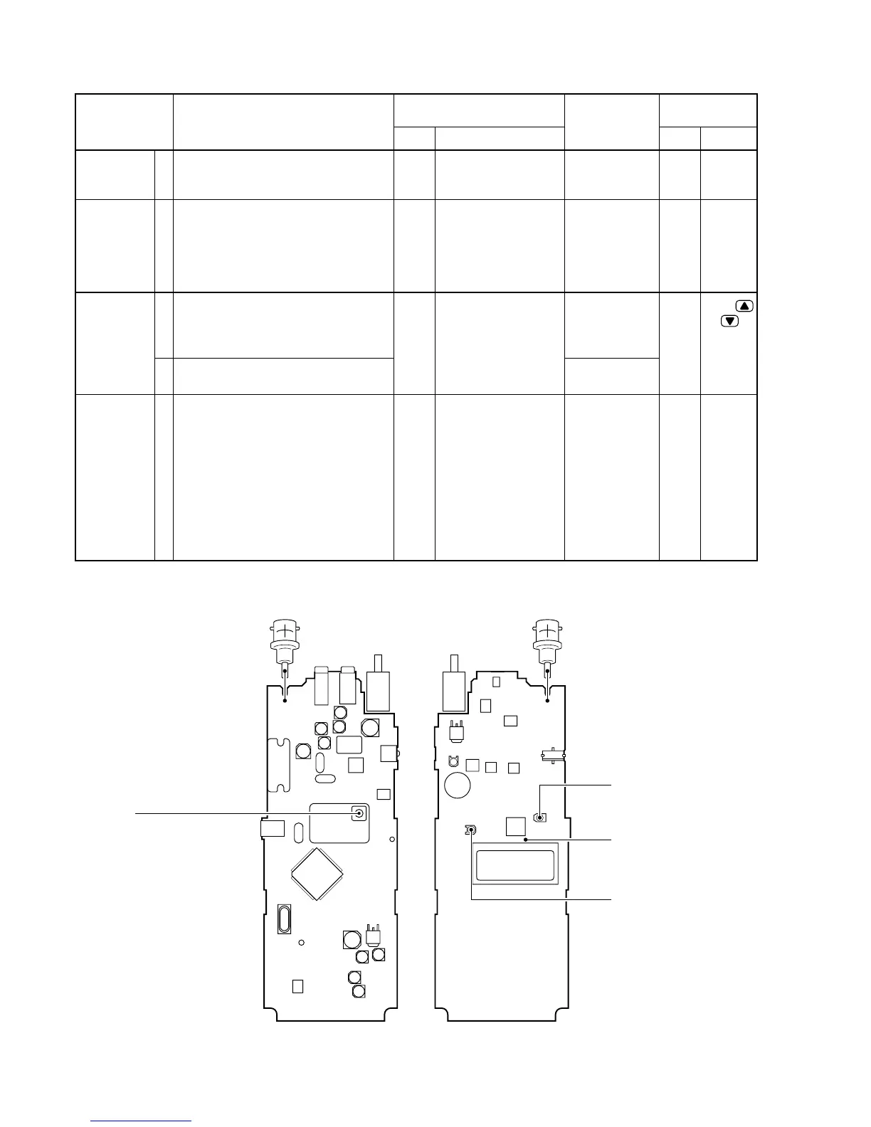
5-2 PLL AND TRANSMITTER ADJUSTMENTS
PLL LOCK
VOLTAGE
REFERENCE
FREQUENCY
OUTPUT
POWER
FM
DEVIATION
ADJUSTMENT
ADJUSTMENT ADJUSTMENT CONDITION
MEASUREMENT
VALUE
POINT
UNIT LOCATION UNIT ADJUST
1.40 V
146.000000 MHz
4.5 W [THA]
5.5 W [other]
1.0 W
±4.5 kHz
1
1
1
2
1
• Operating frequency : 146.000 MHz
• Receiving
• Operating frequency : 146.000 MHz
• Transmitting
• Operating frequency : 146.000 MHz
• HIGH/LOW switch : HIGH
• Connect the “JIG” to the [SP] jack.
• Transmitting
• HIGH/LOW switch : LOW
• Transmitting
• Operating frequency : 146.000 MHz
• HIGH/LOW switch : HIGH
• Connect an audio generator to the
[MIC] jack and set as :
1 kHz/90 mV
• Set an FM deviation meter as:
HPF : OFF
LPF : 20 KHz
De-emphasis : OFF
Detector : (P–P)/2
• Transmitting
MAIN
Top
panel
Top
panel
Top
panel
Connect a digital multi-
meter to the check
point LV.
Connect an RF power
meter or a terminator
to the antenna con-
nector and loosely
couple a frequency
counter.
Connect an RF power
meter to the antenna
connector.
Connect an FM devia-
tion meter to the
antenna connector
through an attenuator.
VCO
board
MAIN
Front
Panel
MAIN
L11
C68
R119

 Loading...