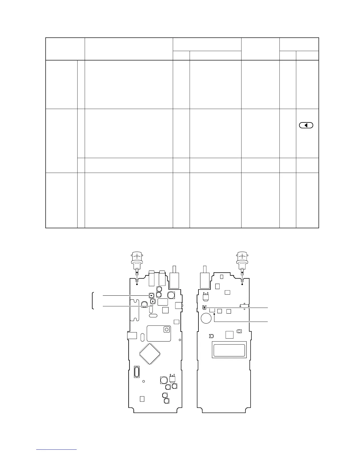
5-3 RECEIVER ADJUSTMENT
SENSITIVITY
S-METER
SQUELCH
ADJUSTMENT
ADJUSTMENT ADJUSTMENT CONDITION
MEASUREMENT
VALUE
POINT
UNIT LOCATION UNIT ADJUST
Maximum level
0.89–0.28 µV
(–106 to –118 dBm)
At the point
where the AF
signals just
disappear.
1
1
2
1
• Operating freq. : 146.000 MHz
• Connect an SSG to the antenna con-
nector and set as:
Frequency : 146.000 MHz
Level : 1 µV* (–107 dBm)
Modulation : 1 kHz
Deviation : ±3.5 kHz
• Receiving
• Operating freq. : 146.000 MHz
• Connect the “JIG” to the [SP] jack.
• Connect an SSG to the antenna con-
nector and set as:
Frequency : 146.000 MHz
Level :
0.5 µV* (–113 dBm)
Modulation : OFF
• Receiving
• Set an SSG output level for the S-
meter to S3 (3 dot).
• Operating freq. : 146.000 MHz
• SQL set : Auto
• Connect an SSG to the antenna con-
nector and set as:
Frequency : 146.000 MHz
Level :
0.1 µV* (–127 dBm)
Modulation : 1 kHz
Deviation : ±3.5 kHz
• Receiving
MAIN
Front
panel
SSG
Spea
ker
Connect a digital volt-
meter to check point S.
LCD
Output level
MAIN
Front
panel
MAIN
Adjust in
sequence
L18, L19
Verify
R92

 Loading...