8
2
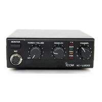
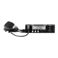
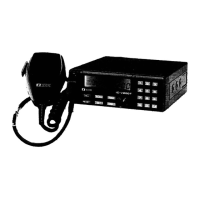
PANEL DESCRIPTION
1
2
3
4
5
6
7
8
9
10
11
12
13
14
15
16
17
18
19
y TONE INDICATOR
➥ “” appears while the subaudible tone encoder is in
use. (p. 23)
➥ “” appears while the tone (CTCSS) squelch function
is in use. (p. 39)
➥ “” appears while the tone (DTCS) squelch function is
in use. (p. 39)
➥ “” appears with the “ ” or “ ” indicator while the
pocket beep function (CTCSS or DTCS) is in use.
(p. 41)
u OUTPUT POWER INDICATOR (p. 19)
➥ “L” appears when the low output power is selected.
➥ “M” appears when the middle output power is selected.
➥ “H” appears when high output power is selected.
i KEY LOCK INDICATOR (p. 20)
Appears when the key lock function is ON.
o FUNCTION INDICATOR
Appears while a secondary function is being accessed.
!0AUTO POWER OFF INDICATOR (p. 52)
Appears while the auto power OFF function is activated.
!1 FREQUENCY READOUT
Shows operating frequency, channel number or channel
names, depending on display type (p. 20).
!2 MEMORY CHANNEL INDICATOR (p. 26)
➥ Shows the selected memory channel number.
➥ “C” appears when the call channel is selected.
!3 MEMORY MODE INDICATOR (p. 26)
Appears while in memory mode or channel number indica-
tion mode.
!4 SKIP CHANNEL INDICATOR (p. 37)
Appears when the selected memory channel is specified
as a skip channel.

 Loading...