4
REMOTE CONTROL
Remote control (CI-V) information
DData format
The CI-V system can be written using the following data formats� Data formats differ according to
command numbers� A data area or sub command is added for some commands�
DCommand table
Command Sub Data Description
00 See p� 6 Send operating frequency for
transceive
01 See p� 6 Send operating mode for transceive
03 See p� 6 Read operating frequency
04 See p� 6 Read operating mode
05 See p� 6 Send operating frequency
06 See p� 6 Send operating mode
07 Select the VFO mode
D0 Select the A band
Dualwatch: Set the MAIN band as
the A band
Single watch: Select the A band
D1 Select the B band
Dualwatch: Set the MAIN band as
the B band
Single watch: Select the B band
0C See p� 6 Read offset frequency*
1
0D See p� 6 Set offset frequency
0F Read duplex setting
(10=OFF, 11=DUP–, 12=DUP+)
10 Set Simplex
11 Set Duplex –
12 Set Duplex +
Command Sub Data Description
11* 00/10/30 Send/read Attenuator
( 00=OFF, 10=10 dB (375 ~ 479 MHz),
30=30 dB (108 ~ 374�995 MHz)
14* 01 See p� 6 Send/read the audio level
03 See p� 6 Send/read the squelch level
0A See p� 6 Send/read the RF power setting
0B See p� 6 Send/read MIC gain (External)
16 See p� 6 Send/read the VOX gain
15 01 00/01 Read noise or S-meter squelch status
(00=Close, 01=Open)
02 0000 ~ 0255 Read S-meter level
(0000=S0, 0170=S9)
05 00/01 Read various squelch function’s
(including the tone squelch) status
(00=Close, 01=Open)
11 0000 ~ 0255 Read the Po Meter Level
( 25=S-Low, 76=Low1,
128=Low2, 179= Mid, 230=High)
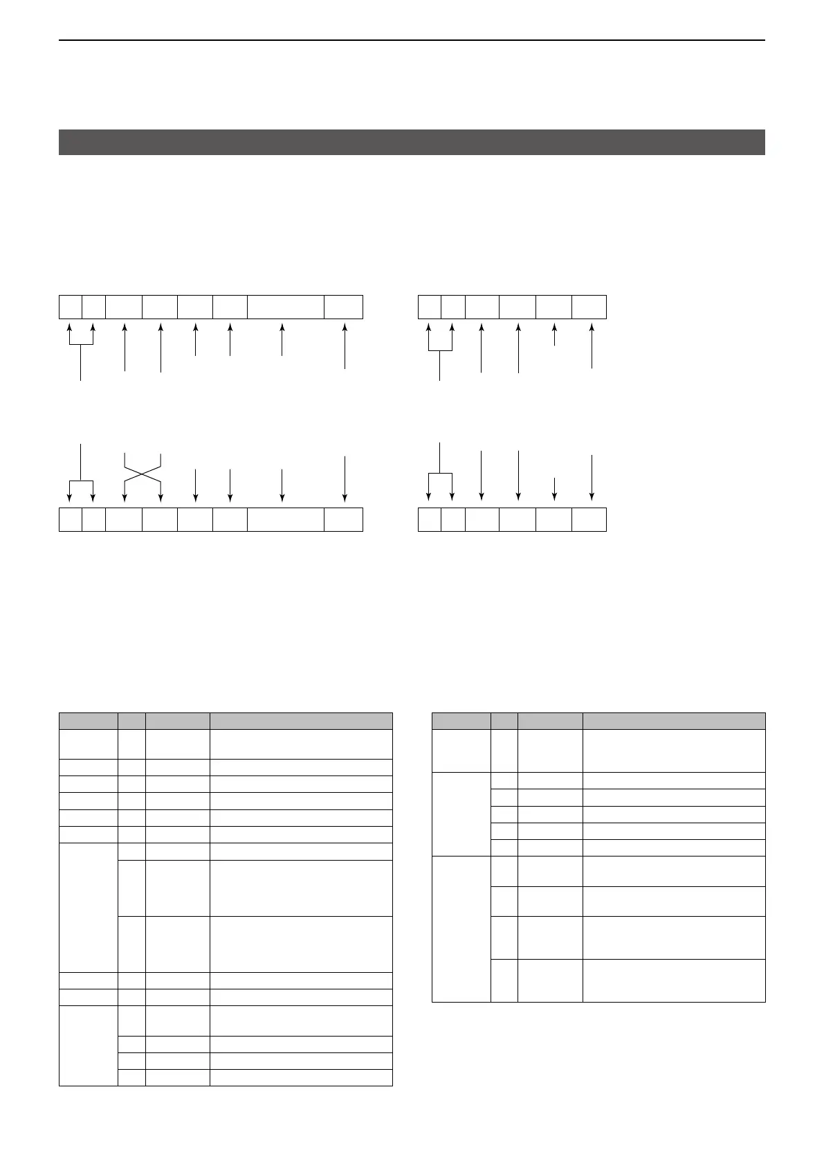
Controller to ID-52A/E OK message to controller
NG message to controllerID-52A/E to controller
FE FE A6 E0 Cn Sc Data area FD
Preamble
code (fixed)
Transceiver’s
default address
Controller’s
default address
Command number
(see the command table)
Sub command number
(see the command table)
BCD code data for
number entry
End of message
code
(fixed)
FE FE E0 A6 FB FD
FE FE E0 A6 FA FD
Preamble
code (fixed)
Controller’s
default address
Transceiver’s
default address
OK code
(fixed)
End of message
code (fixed)
NG code
(fixed)
FE FE E0 A6 Cn Sc Data area FD
*(Asterisk) Send/read data

 Loading...


