General
1. The installation must comply with all relevant national and local
regulations.
2. The installation should be designed to work with ow temperatures
of up to 86
o
C.
3. All components of the system must be suitable for a working
pressure of 3 bar and temperature of 110
o
C. Extra care should
be taken in making all connections so that the risk of leakage is
minimised.
The following components are incorporated within the appliance:
a. Circulating pump.
b. Safety valve, with a non-adjustable preset lift pressure of 3 bar.
c. Pressure gauge, covering a range of 0 to 4 bar.
d. An 8-litre expansion vessel, with an initial charge pressure of 0.75 bar.
4. ‘Make-up’ Water. Provision must be made for replacing water
loss from the system, either :
a. From a manually lled ‘make-up’ vessel with a readily visible
water level. The vessel should be mounted at least 150mm
above the highest point of the system and be connected
through a non-return valve to the system, tted at least 150mm
below the ‘make-up’ vessel on the return side of the radiators.
or
b. Where access to a ‘make-up’ vessel would be difcult, by
pre-pressurisation of the system.
The maximum cold water capacity of the system should
not exceed 143 litres, if not pressurized. However, if the
system is to be pressurized, the efciency of the expansion
vessel will be reduced and a larger vessel (or smaller
system volume) may be necessary. If the capacity of the
vessel is not considered sufcient for this, or for any other
reason, an additional vessel MUST be installed on the
return to the boiler.
Guidance on vessel sizing is given in Frame 2.
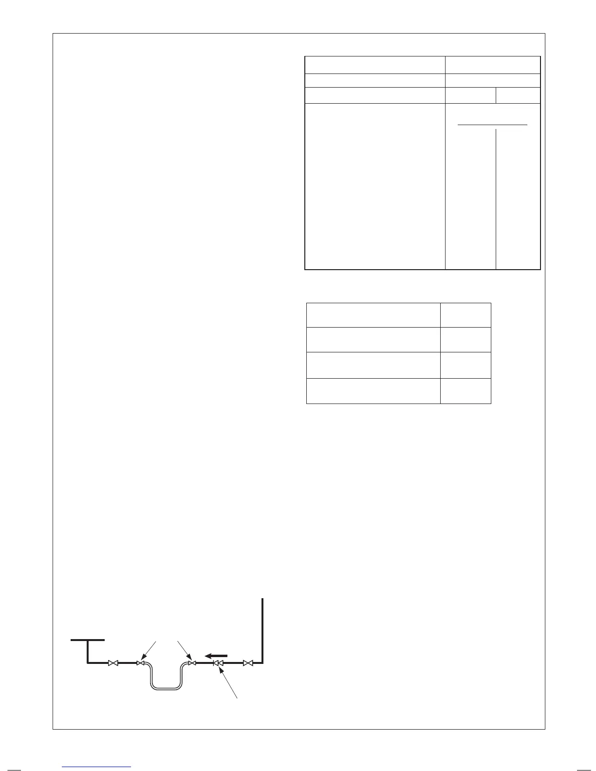
5. Filling - The system may be lled by the following method:
Where the mains pressure is excessive a pressure reducing
valve must be used to facilitate lling.
a. Thoroughly ush out the whole system with cold water.
b. Fill and vent the system until the pressure gauge registers
1bar and examine for leaks.
c. Check the operation of the safety valve by raising the water
pressure until the valve lifts. This should occur within
0.3bar of the preset lift pressure.
d. Release water from the system until the
minimum system design pressure is reached;
1.0 bar if the system is to be pre-pressurised.
Notes
a. The method of lling, relling, topping up or ushing sealed primary
hot water circuits from the mains via a temporary hose connection
is only allowed if acceptable to the local water authority.
b. Antifreeze uid, corrosion and scale inhibitor uids suitable for use
with boilers having aluminium heat exchangers may be used in the
central heating system.
2
SYSTEM REQUIREMENTS - Central Heating
Water Flow Rate and Pressure Loss
Max CH Output kW 24.2
(Btu/h) (82,600)
Water ow rate l/min 17.3
(gal/min) (3.8)
Temperature Differential
o
C 20
(
o
F) (36)
Head available for m.w.g. 3.4
system (ft.w.g.) (11.1)
Safety valve setting bar 3.0
Vessel charge pressure bar 0.5 to 0.75
System pre-charge pressure bar None 1.0
System volume Expansion vessel
(litres) volume (litres)
25 1.6 1.8
50 3.1 3.7
75 4.7 5.5
100 6.3 7.4
125 7.8 9.2
150 9.4 11.0
175 10.9 12.9
190 11.9 14.0
200 12.5 14.7
250 15.6 18.4
300 18.8 22.1
For other system volumes
multiply by the factor across 0.063 0.074
DOMESTIC HOT WATER
1. The domestic hot water service must be in accordance with BS
5546 and BS 6700.
2.
Refer to Table 1 for minimum and maximum working pressures. In
areas of low mains water pressures the domestic hot water regulator
may be removed from the DHW ow turbine cartridge. Refer to
Frame 69. The boiler will require the ow rate to be set to obtain a
temperature rise of 35
o
C at the tap furthest from the boiler.
3. The boilers are suitable for connection to most types of washing
machine and dishwasher appliances.
4. When connecting to suitable showers, ensure that:
a. The cold inlet to the boiler is tted with an approved anti-
vacuum or syphon non-return valve.
b. Hot and cold water supplies to the shower are of equal
pressure.
5. Hard Water Areas
Where the water hardness exceeds 200mg/litre (200ppm), it is
recommended that a proprietary scale reducing device is tted into
the boiler cold supply within the requirements of the local water
company.
IMPORTANT. Provision MUST be made to accomodate the expansion
of DHW contained within the appliance. If the DHW inlet contains a
back ow prevention device or non-return valve, e.g. a water meter,
then a mini expansion vessel should be tted between the device and
the boiler in the cold inlet pipe.
Cold water, rising main & pipework in exposed areas need to be
suitably lagged to prevent freezing.
DHW Expansion Vessel Kit available from Ideal.
CH Return
Hose unions
Mains
water supply
Temporary hose
(disconnect after filling)
Additional
stop valve
Double check valve
assembly
(
note direction of flow
)
 Loading...