29
INITIAL LIGHTING
THE DISPLAY
The user control has one neon and one display to inform
the user about the status. The display will show the status
of the boiler. The neon will show the status of the ame.
If no ame is detected the neon is off. When the ame is
detected the neon will be lit permanently.
Below is a list with display function in normal operation.
Standby, no demand for heat present.
Boiler is active for central heating.
Boiler is active for domestic hot water.
Boiler is heating up the plate heat exchanger.
Boiler is active for boiler frost protection.
Boiler is in lockout for a specic error. Display will be
blinking, alternating with a number or letter to show
which error is detected.
Boiler has a fault for a specic error. Display will be
blinking, alternating with a number or letter to show
which error is detected.
Note: Boiler frost protection - boiler res if temperature is
below 5 degrees C.
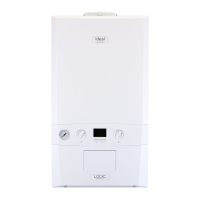
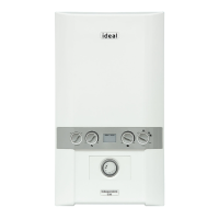
Legend
A. Pre-heat On/off
B. DHW temperature control
C. CH temperature control
D. Off/Summer/Winter/Reset Control
E. Boiler Status
F. Burner ‘on’ indicator
G. CH Flow Isolating Valve
H. Pressure Gauge
J. Gas Inlet Pressure Test Point
K. Gas Service Cock
L. DHW Inlet Valve
M. CH Return Isolating Valve
N. DHW Outlet
1. Check that the system has been lled to the required pressure and that
the boiler is not airlocked. Ensure the automatic air vent cap is open.
Note.
It is important the burner is not operated before the system is fully vented of
air. If it is necessary to operate the appliance pump to assist venting of the
air this must be done with the gas service cock turned off.
2. Ret the boiler front panel. Refer to Frame 34.
3. Check that the drain cock is closed and that the CH and DHW isolating
valves (M, L and G) are OPEN.
4. Check that the electrical supply is OFF.
5. Check that the boiler mode control knob (D) is off.
6. Check that the gas service cock (K) is OPEN.
7. Slacken the screw in the inlet pressure test point (J) and connect a gas
pressure gauge via a exible tube.
8. Switch the electricity supply ON and check mechanical timer is in “Manual
On” position.
Note. The boiler incorporates a fan overrun cycle which
MUST NOT be prematurely interrupted by isolation of the
mains electricity supply.
CENTRAL HEATING
9. Set the CH temp control (C) to max and turn the mode control knob
(D) to
. The boiler control should now go through its ignition
sequence until the burner is established.
10. If the boiler does not light code will be displayed. After 5 attempts
the boiler will lock out and display fault code constantly. Reset
the boiler (Refer to Frame 31). The boiler will repeat its ignition
sequence. If reset occurs 5 times within 15 minutes then
will
be shown. If power is removed this will be reset.
When the burner is established the BLUE ‘Burner On’ neon (F) will
be illuminated, the LED display (E) will show status
.
DOMESTIC HOT WATER
11. With the boiler ring, set the DHW Temp Control knob (B) to
maximum and fully open a DHW tap.
The boiler should continue to run and the LED display (E) should
show status
12. Ensure that with the boiler operating the dynamic gas pressure is
able to obtain maximum output. Refer to Table 2.
IMPORTANT
The gas input to the burner is regulated by the gas valve
accordingtotheairowproducedbythefan.ItisNOT user-
adjustable.Anyinterferencetosealedsettingsonthegasvalve
will adversely affect operation and render our warranty void.
For additional gas supply info refer to “Gas Supply” on page 8.
13. Turn off the DHW tap.
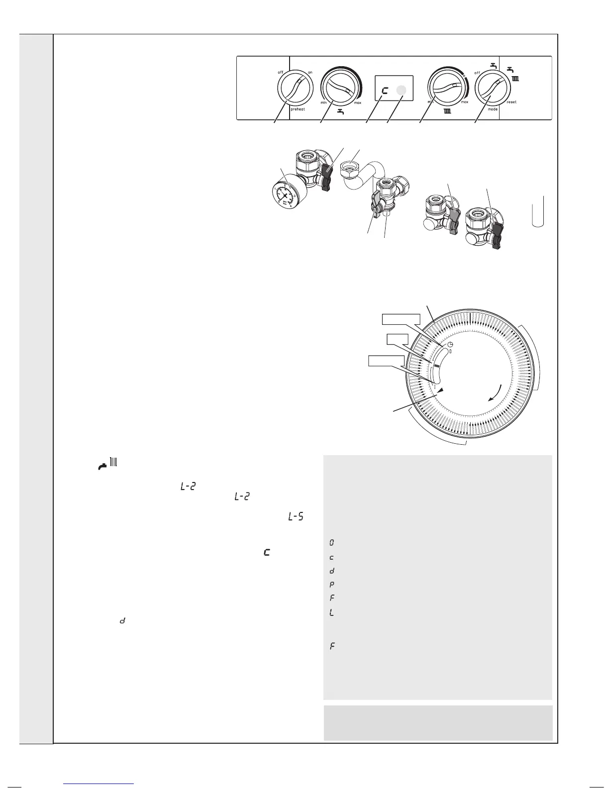
MECHANICAL TIMER
INSTALLATION
 Loading...