3
SEALED SYSTEM REQUIREMENTS
Note. The method of lling, relling, topping up or ushing
sealed primary hot water circuit from the mains for a non-
domestic property is shown below.
1. General
a. Detail reference should be made to the appropriate
standards listed on page 8. The information and guidance
given below is not intended to override any requirements
of these publications or the requirements of the local
authority, gas or water undertakings.
b. The installation should be capable of working with ow
temperatures of up to 90
o
C and a temperature differential
of up to 20
o
C.
c. All components of the system, including the heat
exchanger of the indirect cylinder, must be suitable for a
working pressure of 4 bar (60 lbf/in
2
) and temperature of
110
o
C. Care should be taken in making all connections so
that the risk of leakage is minimised.
d. The boiler is tted with an automatic air
vent, located in the left top side of the
interior. This air vent must never be shut
off, as this could result in dry ring of the
boiler and subsequent damage to the heat
exchanger.
2. Safety Valve
A spring loaded safety valve complying with
the relevant requirements of BS. 6759 Pt. 1
must be tted in the ow pipe as close to the
boiler as possible and with no intervening
valve or restriction. The valve should have the
following features:
a. A non-adjustable preset lift pressure not
exceeding 4 bar (60 lbf/in
2
).
b. A manual testing device.
c. Provision for connection of a discharge pipe. The valve or
discharge pipe should be positioned so that the discharge
of water or steam is visible, but will not cause hazard to
user or plant.
3. Pressure Gauge
A pressure gauge covering at least the range 0-4bar must be
tted to the system. The gauge should be easily seen from
the lling point and should preferably be connected at the
same point as the expansion vessel.
4. Expansion Vessel
Expansion vessels used must comply with BS. EN 13831.
Connection to the system must not incorporate an isolating
valve.
2
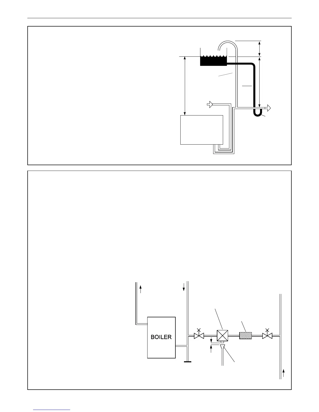
OPEN VENTED SYSTEM REQUIREMENTS
Detail reference should be made to the appropriate standards
listed on page 8.
The information and guidance given below is not intended
to override any requirements of the above publications or the
requirements of the local authority, gas or water undertakings.
The vertical distance between the pump and feed/expansion
cistern MUST comply with the pump manufacturer’s minimum
requirements, to avoid cavitation. Should these conditions
not apply either lower the pump position or raise the cistern
above the minimum requirement specied by Ideal Boilers.
The isolation valves should be tted as close to the pump as
possible.
The boiler is tted with an automatic air vent, located in the left
top side of the interior. This air vent must never be shut off,
as this could result in dry ring of the boiler and subsequent
damage to the heat exchanger.
 Loading...