CONTENTS
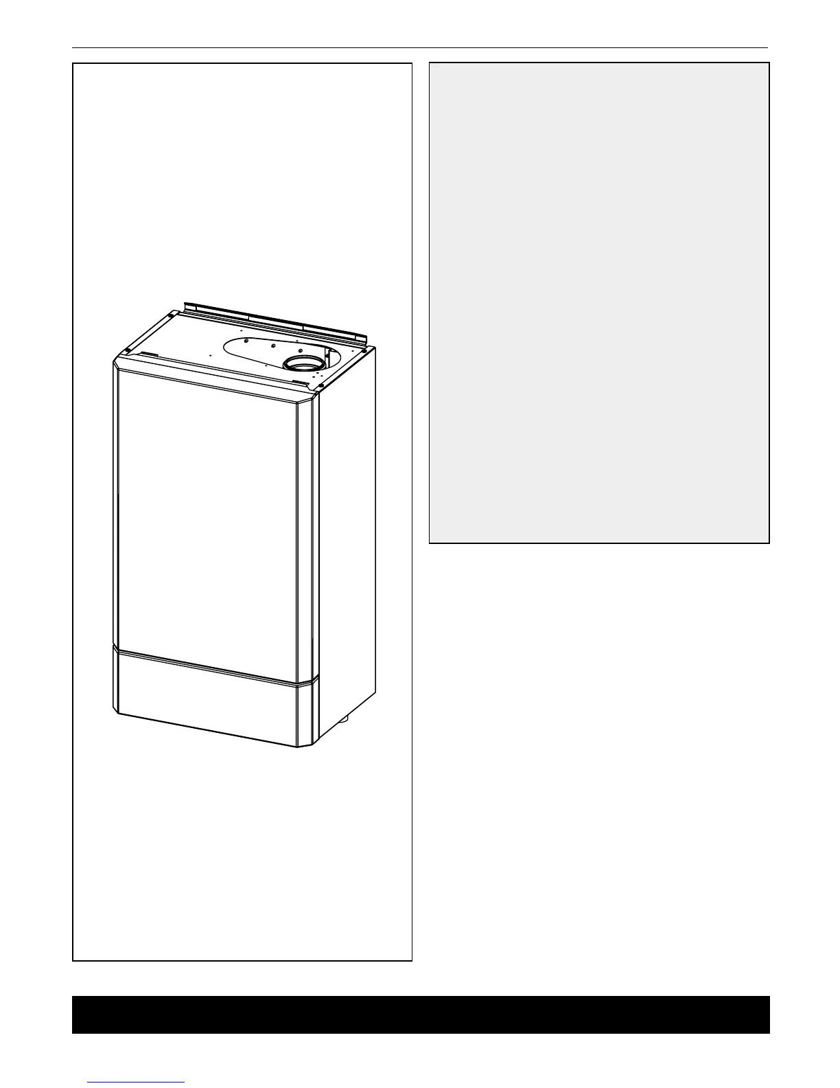
Boiler Assembly - Exploded view. .................................13
Boiler Clearances. ...........................................................11
Commissioning and Testing. ..........................................44
Electrical Connections. ................................................... 29
Electrical Supply..............................................................10
Fault Finding. ...................................................................55
Flue Installation. ................................................................9
Flue Kits. ..........................................................................17
Gas Safety Regulations ...................................................8
Gas Supply. ........................................................................ 9
Hydraulic Resistance. .....................................................10
Introduction. .......................................................................8
Initial Lighting. .................................................................45
Installer Connections. .....................................................30
Installation. .......................................................................13
Mounting Boiler. ..............................................................16
Option Kits. ........................................................................8
Performance Data. ............................................................. 6
Servicing. .........................................................................47
Short List of Parts. ..........................................................65
Ventilation. .......................................................................16
Water Circulation. .............................................................. 9
Water Connections. ......................................................... 28
Water System Requirements. .........................................12
Water Treatment. .............................................................10
Wiring Diagrams. .............................................................31
Key to symbols
IE = Ireland, GB = United Kingdom (Countries of destination)
PMS = Maximum operating pressure of water
C13 C33 = A room sealed appliance designed for
connection via ducts to a horizontal or vertical
terminal, which admits fresh air to the burner
and discharges the products of combustion
to the outside through orices which, in this
case, are concentric. The fan is up stream of
the combustion chamber.
B23 = An appliance intended to be connected
to a ue which evacuates the products
of combustion to the outside of the room
containing the boiler. The combustion air is
drawn directly from the room. The fan is up
stream of the combustion chamber.
II2H3P = An appliance designed for use on 2nd and 3rd
Family gases.
NOTE TO THE INSTALLER:
LEAVE THESE INSTRUCTIONS ADJACENT TO THE GAS METER.
INSTINCT HEAT
40, 60, 80, 100, 120, & 150
40P, 60P & 80P
Natural Gas & LPG
PI No. 86 CL 166
Destination Countries: GB, IE
 Loading...