Permanent
230Vac
Mains
Supply
Optional
230Vac
Call for CH
Optional
230Vac
Call for HW
Optional
230Vac
DHW
Pump or
Diverter
Valve
Output
Optional
230Vac
CH or
System
Pump
Output
Optional 5V
OpenTherm
Input
Optional
5V Outside
Sensor
Input
Optional 5V
DHW Tank
Sensor
Input
Optional
0-10V
Input
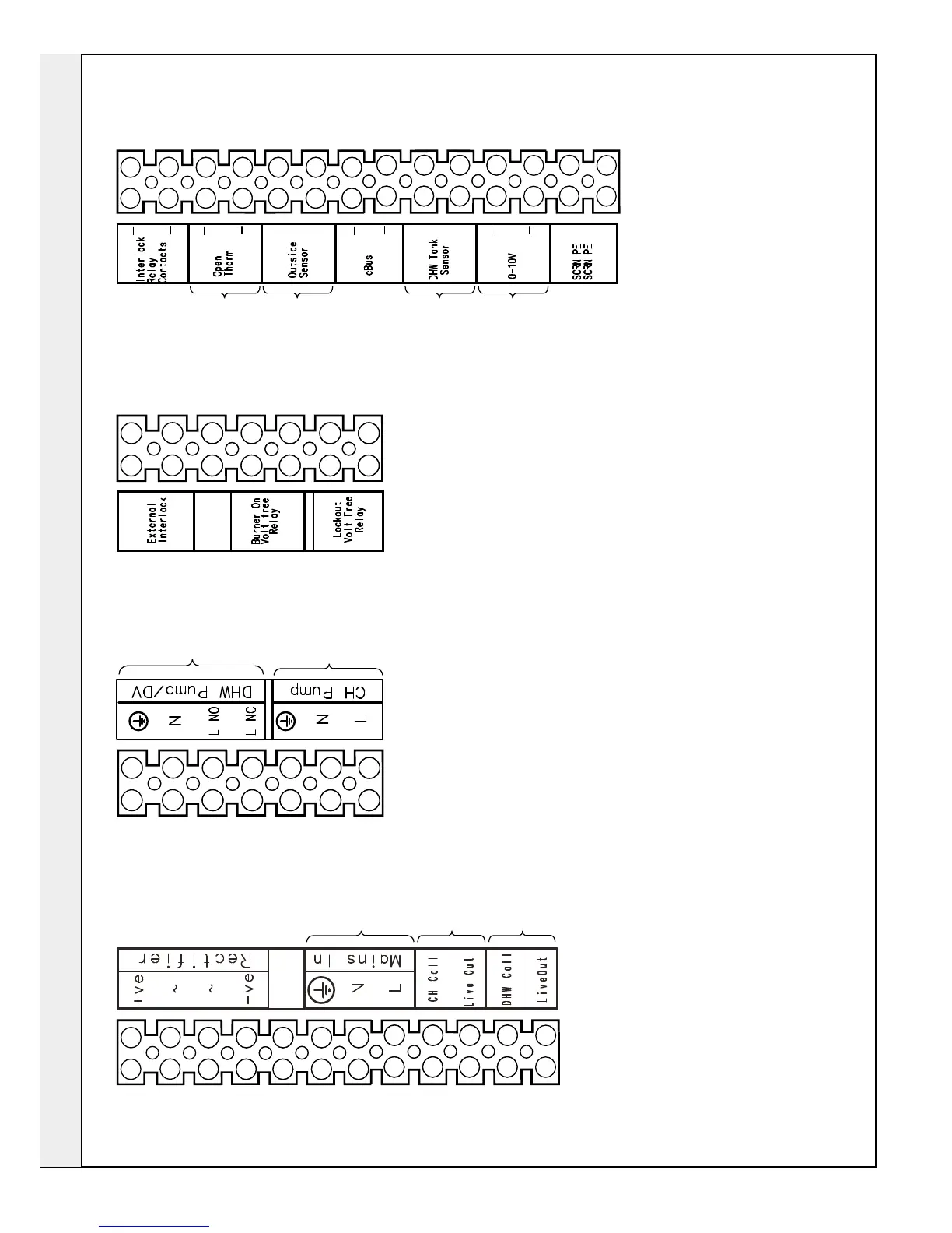
1. If a Pump is to be run from the boiler and the electrical current draw is 1.3A inductive or less then the pump can be connected directly into the CH Pump or DHW Pump connections,
as appropriate (e.g. Grundfos 40/60 UPS is satisfactory). If the current draw is more than this (eg a Grundfos 40/120 UPS) then an external relay should be operated by the
CH Pump or DHW Pump connections, with the external relay then powering the pump.
2. The Lockout Volt Free Relay contacts will close 4 minutes after a Fault occurs.
3. The Burner On Volt Free Relay contacts will close when the Burner is on.
4. Only Ideal Outside Sensor and DHW Tank Sensor kits should be connected to the boiler.
5. The External Interlock and Interlock Relay Contacts connections are only used in conjunction with the External Interlock Kit.
6. The Rectifier connections must not be used (only used in the existing internal boiler wiring).
7. The eBus connections are not for use.
 Loading...