SERVICING
60
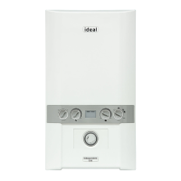
HEAT EXCHANGER INSPECTION / CLEANING
59
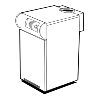
BURNER REMOVAL
1. Refer to Frame 55.
2. Remove the front panel (Refer to frame 57)
3. Remove the fan and gas valve assembly (Refer to frame 58)
4. Remove the six/eight extended nuts securing the burner to release
the burner body.
5. Lift the burner body to remove it from the studs and lift the burner
out of its recess.
6. The burner can now be cleaned on the back face only, the metal
bre surface must not be touched. The burner must be replaced if it
shows signs of damage.
7. After cleaning the burner replace it in the recess and check the burner body seal for signs of damage. If damage is apparent it
must be replaced.
8. Reassemble in reverse order. The six (or eight) extended nuts should be tted following a diagonal tightening sequence twice.
The nuts should be secured rmly.
9. Check the operation of the boiler (Refer to Frame 55).
1. Refer to Frame 55.
2. Remove the front panel (Refer to frame 57)
3. Remove the fan and gas assembly (Refer to frame 58)
4. Remove the burner (Refer to frame 59)
5. Remove the ignition and detection electrodes (Refer to frame
66/67)
6. Inspect the heat exchanger for signs of aluminium oxide
deposits. If necessary clean the heat exchanger by spraying
water down the ue ways.
7. Reassemble in reverse order replacing all gaskets.
8. Check the operation of the boiler (Refer to frame 55)
4
61
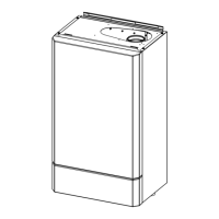
REMOVAL OF SUMP COVER
1. Refer to Frame 55.
2. Remove the front panel (Refer to frame 57)
3. Prepare boiler for possible water spillage during
the process.
4. Remove the two screws from the helmholtz/clean-
out cover and pull away from the boiler.
5. Scrape out any deposits.
6. Reassemble in reverse order replacing all gaskets.
4
4
Models 40, 150
Models 60, 80, 100 & 120
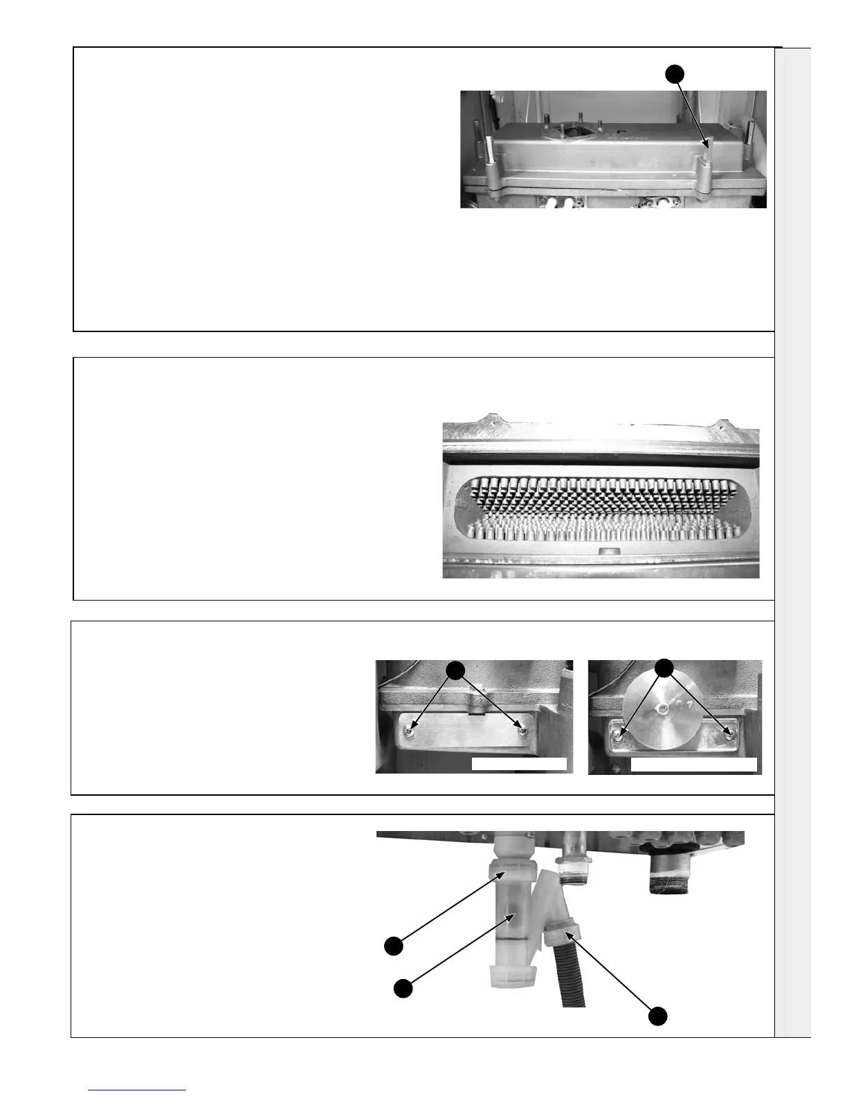
1. Refer to Frame 55.
2. Unscrew the nut and disconnect the exible
pipe.
3. Unscrew the top nut and remove the
condensate trap.
4. Remove the ball from the condensate trap and
ush out with water to remove any debris.
5. Reassemble in reverse order.
6. Check the operation of the boiler (Refer to
frame 55)
62
CONDENSATE TRAP
3
4
2
 Loading...