8
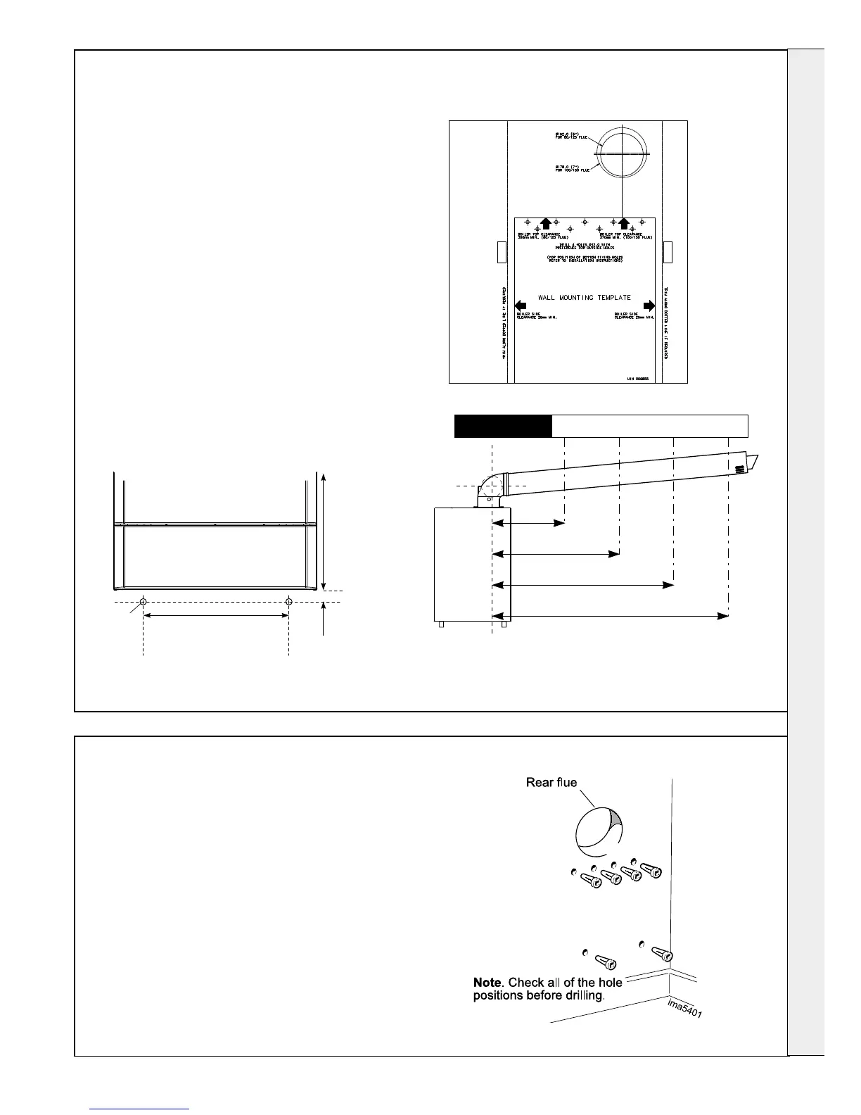
PREPARING THE WALL
7
WALL MOUNTING TEMPLATE
Note. The template shows the positions for the
top xing holes. Care must be taken to ensure
the correct holes are drilled.
1. Tape template into the selected position.
2. Ensure squareness by hanging a plumbline.
3. Mark on to the wall:
a. The top 4 wall mounting plate screw
positions.
b. The 2 boiler lower xing positions using
diagram below
c. The position of the ue duct. Mark
the centre of the hole as well as the
circumference.
4. Remove the template from the wall.
IMPORTANT. Ensure that, during the cutting
operation, masonry falling outside of the building
does not cause damage or personal injury.
1. Cut the ue hole ensuring that the hole
is square to the wall. Both wall faces
immediately around the cut hole should be at.
2. Drill 4 boiler top xing holes with a 12mm
(
1
/
2
”) masonry drill and insert the plastic plugs
provided, for the wall mounting plate.
3. Drill the 2 boiler lower xing holes with a 12mm
(
1
/
2
”) masonry drill, insert the plastic plugs
provided .
4. Fix the wall bracket into place with 4 M10x70
hex head coach screws provided.
ima5400
X
Y
26 52 78 104
Vertical Offset From X mm
Distance from flue centre line (Y) to outside wall surface.
For lengths greater than 4m, increase offset (X) by 26mm
for every additional 1m.
4m
3m
2m
1m
 Loading...