16
CUTTING & SETTING THE FLUE LENGTH
CUT 75MM OFF HORIZONTAL FLUE TERMINAL 1000MM LONG B PACK (TELESCOPIC)
1. Measure cut ue length (A+44mm). (If required telescopic length is not between
658 and 708 then proceed to “Setting Telescopic Flue B Pack”).
2. Remove telescopic end piece from the ue body and set aside.
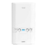
3. Mark the circumference 75mm from the open end of the outer ue.
4. Cut along the 75mm mark cutting onlytheouterue ensuring the cut is square.
5. Dress the cut end to make sure all burr is removed and the cut edge is in its
original shape.
6. Measure 20mm from the newly cut edge of the outer ue, place a mark at the top of the ue approximately 20mm wide &
write stop the terminal side of the line.
7. Mark the inner tube 10mm longer than the outer tube around its circumference and cut following the mark to ensure its cut
square
8. Remove all burrs and place a chamfer on the outer edge to aid assembly.
9. Re-assemble telescopic section.
SETTING TELESCOPIC FLUE B PACK
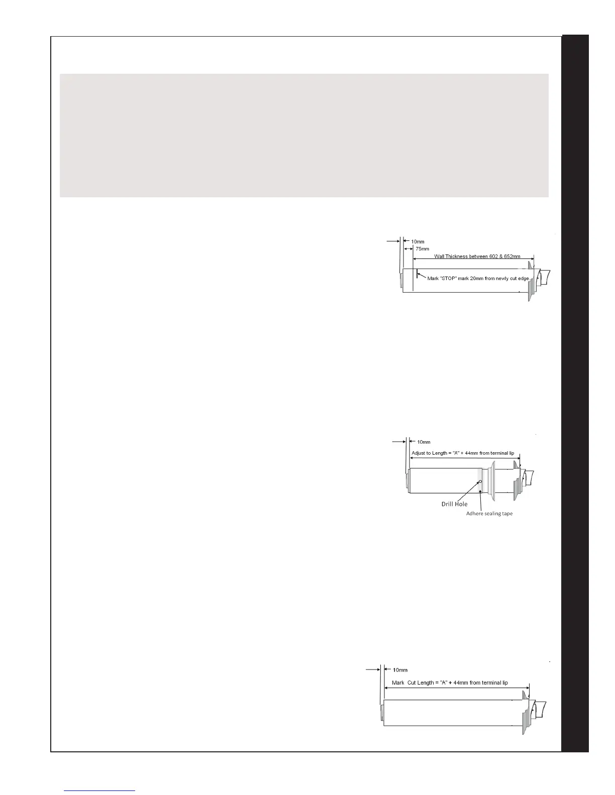
1. Measure the required ue length (A+44mm).
2. Measure from the outer terminal lip to end of outer ue. Pull apart ue until
desired length is achieved. ENSURE THE STOP MARK IS NOT VISIBLE,
IF IT IS, THE FLUE IS TOO SHORT AND SHOULD NOT BE USED.
3. Check that both ue seams are at the top and the outlet terminal is upper
most.
4. Drill a 3.5mm hole through one of the 2 outer side holes in the outer ue
section into the inserted outer ue (as shown). Take care not to pierce the
inner plastic ue. Fit screw provided.
5. Seal the joint on the outer air duct with the tape provided.
6. Fit internal and external wall seals (see installing ue)
CUTTING HORIZONTAL FLUE TERMINAL (600MM LONG) B PACK
1. Measure the required cut ue length (A+44mm). If inside the dimensions
shown in Figure 2 “1 Piece 600mm” proceed.
2. Measure from the outer terminal lip to end of outer ue. Mark the
required cut length (A+44) around the circumference of the outer ue and
cut following the mark to ensure its cut square.
3. Dress the cut end to make sure all burr’s are removed and the cut edge
is in its original shape.
4. Mark the inner tube 10mm longer than the outer tube around its
circumference and cut following the mark to ensure its cut square.
5. Remove all burrs and place a light chamfer on the outer edge to aid
assembly.
TELESCOPIC FLUES
TELESCOPIC FLUE B PACK SHOULD ONLY BE ADJUSTED FOR USE WITHIN ITS SPECIFIED RANGE AND MUST NOT
BE CUT
HORIZONTAL FLUE TERMINAL (1000MM LONG) B PACK (TELESCOPIC) MUST ONLY BE CUT IF REQUIRED FLUE
LENGTHS ARE BETWEEN 602 & 652MM. THIS WILL REQUIRE 75MM TO BE CUT OFF THE TERMINAL END OF THE
1000MM TELESCOPIC FLUE.
ALL OTHER LENGTHS OBTAINED USING “D” PACK EXTENSIONS IN FLUE LENGTH TABLE 1, COLUMN “HORIZONTAL
FLUE TERMINAL (1000MM LONG) B PACK CUT 75MM” (TELESCOPIC) SHOULD HAVE THE 75MM CUT OFF THE “D”
PACK EXTENSION AND NOT TELESCOPIC FLUE
 Loading...