32
INITIAL LIGHTING
1. Check that the system has been lled to the required pressure
and that the boiler is not airlocked. Ensure the automatic air vent
cap is open. Refer to Frame 24.
Note.
It is important the burner is not operated before the system is fully
vented of air. If it is necessary to operate the appliance pump to
assist venting of the air this must be done with the gas service cock
turned off.
2. Ret the boiler front panel. Refer to Frame 39.
3. Check that the drain cock is closed and that the CH and DHW
isolating valves (M, L and G) are OPEN.
4. Check that the electrical supply is OFF.
5. Check that the boiler mode control knob (D) is off.
6. Check that the gas service cock (K) is OPEN.
7. Slacken the screw in the inlet pressure test point (J) and connect
a gas pressure gauge via a exible tube.
8. Switch the electricity supply ON and check all external controls
are calling for heat.
CENTRAL HEATING
9. Set the CH temp control (C) to max and turn the mode control
knob (D) to
, ensure the timer/room stat are on. The boiler
control will now go through its ignition sequence until the burner
is established.
10. If the boiler does not light the following messages will be
displayed in rotation “Ignition Lockout” - “1 Check other gas
appliances” - “2 Reset boiler” - “3 Contact installer”.
After 5 attempts the boiler will lock out and carry on displaying
the messages. Reset the boiler (refer to Frame 35). The boiler
will repeat its ignition sequence. If reset occurs 5 times within
15 minutes then “Too many resets” will be shown. If power is
removed this will be reset.
When the burner is established the BLUE ‘Burner On’ neon (F)
will be illuminated, the LCD will display “Central Heating” and
“Radiator Temp XX
o
C”.
DOMESTIC HOT WATER
11. With the boiler ring, set the DHW Temp Control knob (B)
to maximum and fully open a DHW tap.
The boiler will continue to run and the display (E) will
show “Hot Water” - “Temperature XX
o
C” - “High
Efciency”.
12. Ensure that with the boiler operating the dynamic gas
pressure is able to obtain maximum output. Refer to Table
2.
IMPORTANT
The gas input to the burner is regulated by the gas valve
accordingtotheairowproducedbythefan.ItisNOT
user-adjustable.Anyinterferencetosealedsettingson
the gas valve will adversely affect operation and render
our warranty void.
For additional gas supply information refer to “Gas Supply” on
page 8
13. Turn off the DHW tap.
continued. . . . .
Note. The temperature displayed “XXºC” is that
measured at that moment, not the set temperature.
Note. The boiler incorporates a fan overrun cycle
which MUST NOT be prematurely interrupted by
isolation of the mains electricity supply.
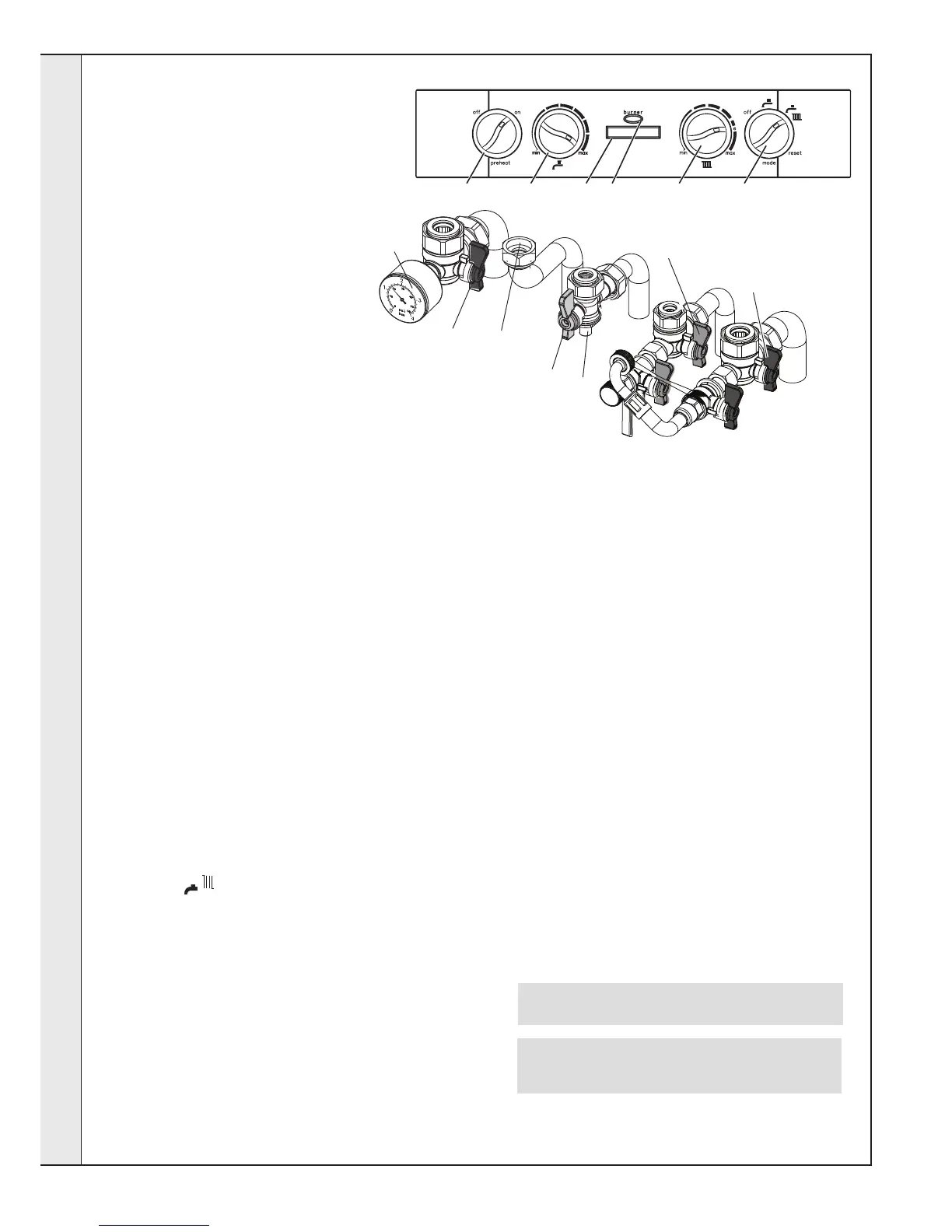
Legend
A. Pre-heat On/off
B. DHW temperature control
C. CH temperature control
D. Off/Summer/Winter/Reset Control
E. Boiler Status
F. Burner ‘on’ indicator
G. CH Flow Isolating Valve
H. Pressure Gauge
J. Gas Inlet Pressure Test Point
K. Gas Service Cock
L. DHW Inlet Valve
M. CH Return Isolating Valve
N. DHW Outlet
G
H
J
L
N
M
K
 Loading...