26
INTERNAL WIRING
The Logic + Combi boiler comes pre-tted with 1.8m of
mains cable. This must be connected to a permanent live
supply and NOT switched by thermostats/programmers.
For installers wishing to change this cable refer to Frame
33.
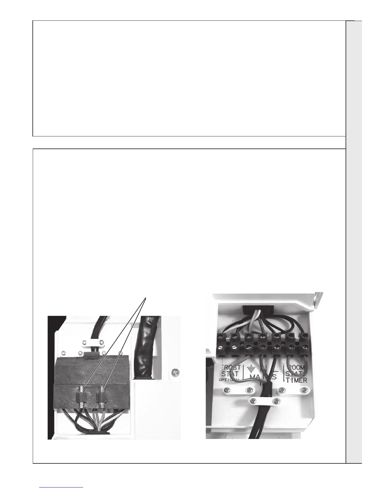
The Logic + Combi boiler comes pre-tted with a link
wire between the room thermostat/Timer connections on
the terminal strip. This creates a permanent call for heat
and must be removed when adding a room thermostat/
programmer.
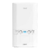
The terminal block cover carries two spare fuses for the
main PCB.
To add thermostat/programmer:
1. Isolate the mains supply to the boiler.
2. Remove the front panel. Refer to Frame 39.
3. Swing the control box down into the servicing position. Refer to
Frame 45.
4. Route incoming cables through the grommets in bottom panel
(note, grommets are ‘blind’ and will require puncturing) and
secure using clamps and screws provided in hardware pack.
5. Pull off rubber terminal block cover.
6. Connect wires to terminal block, as shown below
7. Re-assemble in reverse order.
continued . . . .
25
ELECTRICAL CONNECTIONS
Wiring should be 3 core PVC insulated cable, not less than
0.75mm
2
(24 x 0.2mm), and to BS 6500 Table 16. For IE
reference should be made to the current ETCI rules for
electrical installations.
Connection must be made in a way that allows complete
isolation of the electrical supply such as a double pole switch
having a 3mm (1/8”) contact separation in both poles. The
means of isolation must be accessible to the user after
installation.
WARNING. This appliance MUST be earthed.
A mains supply of 230Vac ~ 50 Hz is required.
The fuse rating should be 3A. All external controls and wiring
must be suitable for mains voltage.
Wiring external to the boiler MUST be in accordance with the
current I.E.E. (BS.7671) Wiring Regulations and any local
regulations.
Spare PCB fuses
INSTALLATION
 Loading...