Ideal offer 5 kits as follows:
(see individual kits for installation instructions)
Mechanical Timer (24 hr) Kit - 24 hour mechanical CH timer ts into the control box of the boiler. This can be tted in conjunction
with a room thermostat.
Electronic Timer (7 day) kit - 7 day electronic CH timer ts into the control box of the boiler. This can be tted in conjunction with a
room thermostat. Features English language installation help messages.
RF Mechanical Programmable Room Thermostat (24 hr) kit - Combined 24 hour mechanical timer and room thermostat with
wireless communication to receiver unit which ts into control box of the boiler.
RF Electronic Programmable Room Thermostat (7 day) kit - Combined 7 day timer and room thermostat with wireless
communication to receiver unit which ts into control box of the boiler. Features English language installation help messages. Also
OpenTherm Control for gas consumption saving.
Weather Compensation Kit -
Allows outside temperature sensing.
27
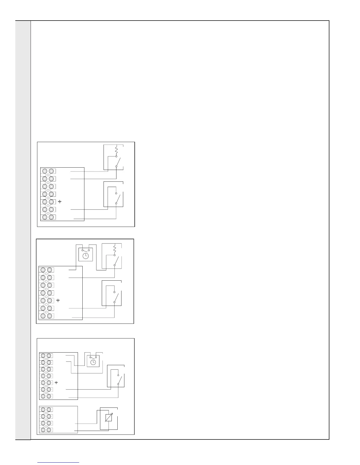
INTERNAL WIRING CONT’D
(1) ROOM THERMOSTAT WITH INTERNAL BOILER TIMER OR
(2) PROGRAMMABLE ROOM THERMOSTAT
1. Remove link wire between room stat/timer terminals.
2. Connect room stat across terminals as shown in diagram A
3. If room stat has a neutral connection, connect this to terminal
N (load) in the fused spur.
ROOM THERMOSTAT + TIMER
1. Remove link wire between room stat/timer terminals.
2. Connect room stat and programmer in series as shown in diagram B.
3. If room stat has a neutral connection, connect this to terminal N (load) in the
fused spur.
FROST THERMOSTAT
If parts of the system are vulnerable to freezing or the programmer is likely to be
left off during cold weather, a frost stat should be tted in conjunction with a pipe
thermostat.
1. Position the frost thermostat in a suitable position, i.e. area vulnerable to
freezing.
2. Connect frost stat across terminals marked frost stat shown in diagrams A & B.
WEATHER COMPENSATION KIT
The two wires from the weather compensation kit (outside sensor), must be
connected into the two right hand terminals as shown in diagram C.
INSTALLATION
 Loading...