31
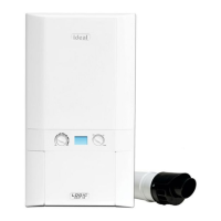
ASSEMBLING THE ROOF FLUE KIT
Determine the correct height that the ue should terminate
above the roof. If after calculating or measuring the overall ue
height from the top of the boiler, it is necessary to cut both pipes
of assembly A, then ensure they are cut equally leaving the inner
ue tube longer than the outer air tube as supplied.
Ensure the cut pipe ends are free from any burrs.
1. Position the roof ashing plate (supplied separately) over the
hole cut in the roof and insert ue terminal from the roof end.
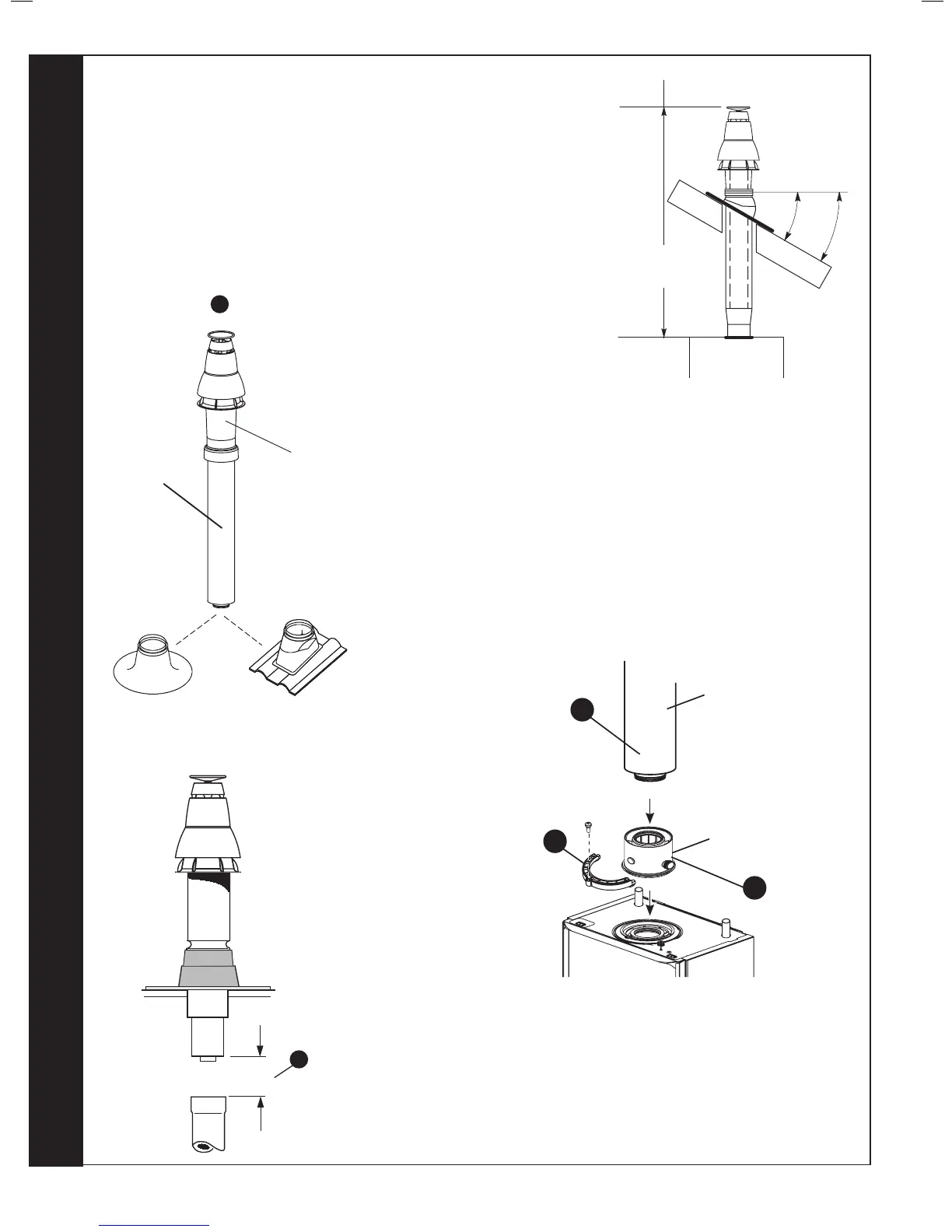
2. Fit the vertical connector (supplied separately) in accordance
with the instructions provided with the vertical connector kit.
3. Secure the vertical connector by applying downward pressure
on the connector.
4. Position the clamp on the top face of the ue manifold and push
it horizontally backwards. Locate both clamp lugs into the ue
manifold and secure to the ue manifold with the M5 retaining
screw.
5. “Push” t extension duct (if required (supplied separately)) into
vertical connector.
Note. Ensure turret sample points are servicable and all caps and
plugs are tted.
6. If the last extension duct requires cutting, measure ‘X’, the distance
(outer ducts), between the duct and the terminal and add 100 mm to this
dimension. This gives the length of the last extension duct.
Note. Check the position of the inner ue duct relative to the outer duct on
the assembled extension duct(s) and ensure the terminal ue duct is cut
longer than the air duct to ensure engagement in the nal ue duct seal.
7. Finally ensure the roof ashing plate is correctly sealed to the roof.
ASSEMBLY A
 Loading...