38
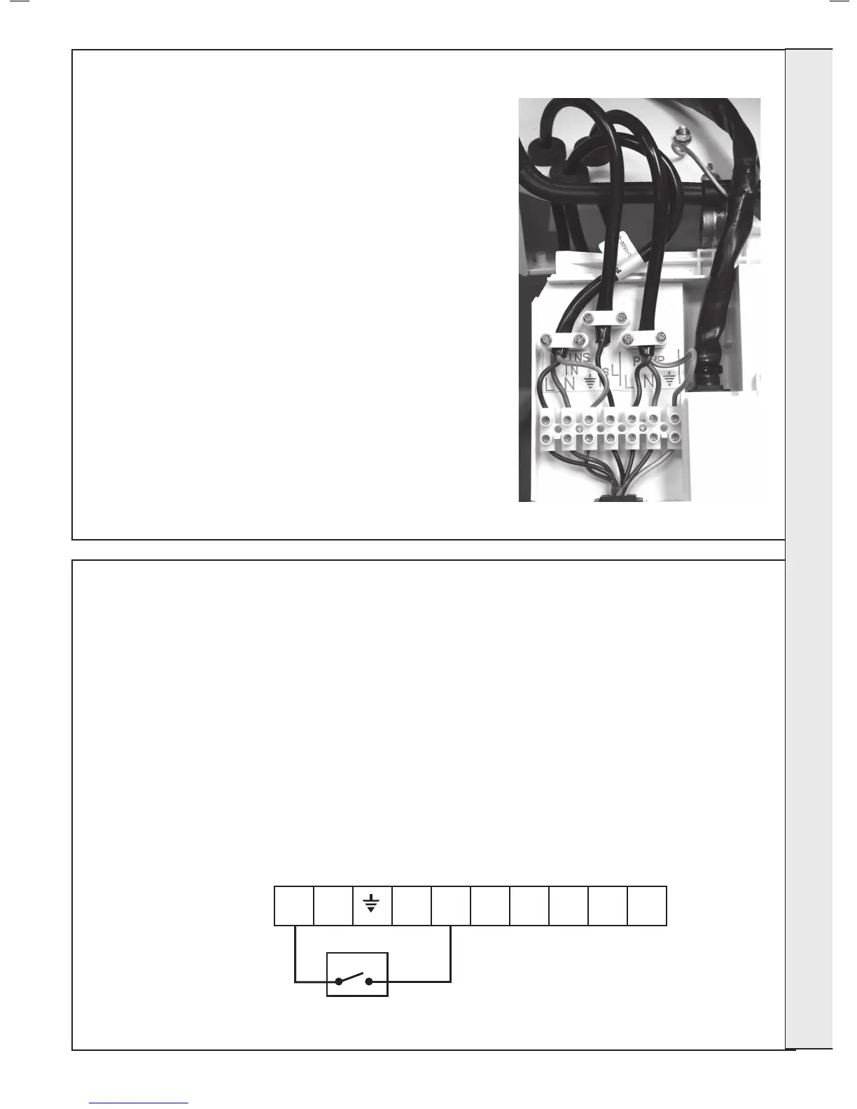
EXTERNAL ELECTRICAL CONTROLS
Wiring External to the Boiler
The fuse rating should be 3A.
Wiring external to the boiler MUST be in accordance with the current
I.E.E. (BS.7671) Wiring Regulations and any local regulations.
Difculty in wiring should not arise, providing the following directions
are observed:
1. The appliance must be wired with a permanent live supply.
External controls should NOT be wired in series with this mains
input. Controlling the mains input in this way will prevent the pump
overrrun sequence and may cause damage to the heat exchanger.
2. 230V AC output is provided and must be used for the system
pump. Care must be taken to ensure that the earth conductor is
longer than the current carrying conductors for reasons given in
Frame 41 - item 6.
3G9503b
L N
CH
ON
HW
ON
R/S
ON
HW
OFF
C/S
ON
Earths are not shown for clarity but must
never be omitted.
37
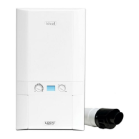
WIRING THE SYSTEM PUMP
NOTE. THE APPLIANCE MUST BE WIRED WITH A PERMANENT LIVE
SUPPLY. THE SYSTEM PUMP MUST BE WIRED TO THE BOILER. THE
BOILER WARRANTY WILL BE INVALID IF THIS REQUIREMENT IS NOT
COMPLIED WITH.
1. Isolate the mains supply to the boiler.
2. Remove the front panel. Refer to Frame 12.
3. Swing the control box down into the service position.
4. Loosen the pump wire cable clamp.
5. Route pump cable through the cable clamp and grommet and re-tighten
to provide cord anchorage.
6. Connect the live, neutral and earth wires to the terminal strip. When
making the mains electrical connections to the boiler it is important that
the wires are prepared in such a way that the earth conductor is longer
than the current carrying conductors, such that if the cord anchorage
should slip, the current carrying conductors become taut before the
earthing conductor.
7. Swing the control box back up into the operating position and re-t the
front panel ensuring a good seal is made.
Note.
For multiple boiler installations with a common pump, the pump connection
should be made directly from each boiler to the same pump, as long as all
the boilers are on the same phase.
Frost Protection
If parts of the pipework run outside the house or if the
boiler will be left off for more than a day or so then a
frost thermostat should be wired into the system.
The frost thermostat should be sited in a cold place but
where it can sense heat from the system.
Note. If the boiler is installed in a garage it may be
necessary to t a pipe thermostat, preferably on the
return pipework.
INSTALLATION
 Loading...