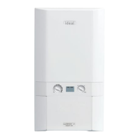
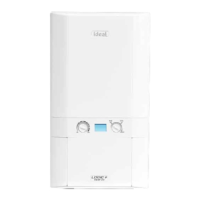
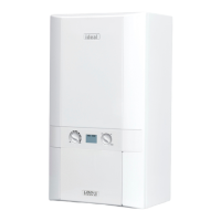
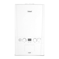
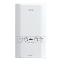
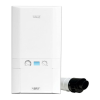
Boiler size G.C. Appliance No. PI No.
(Benchmark No.)
15 41-750-57 86 CL 08
24 41-750-58 86 CL 08
CONTENTS
Air Supply ...................................................................... 9
Benchmark Commissioning Checklist ..................... 58
Boiler Clearances ....................................................... 10
Boiler Exploded Diagram ........................................... 15
Condensate Drain .......................................... 9,29,30,46
Commissioning & Testing ......................................... 35
Electrical Connections ............................................... 31
Electrical Supply ........................................................... 9
Fault Finding ............................................................... 50
Flue Fitting .................................................................. 19
Flue Installation ............................................................ 8
Gas Safety Regulations ............................................... 7
Gas Supply .................................................................... 8
Initial Lighting ............................................................ 36
Installation ............................................................. 15-37
Safe Handling ................................................................ 6
Servicing ................................................................ 38-49
Spare Parts Info .......................................................... 55
Thermostatic Radiator Valves ..................................... 9
Water and Systems ........................................... 9,11-14
Water & Gas Connections ......................................... 31
Water Treatment ........................................................ 14
Wiring Diagram ........................................................... 34
Natural Gas only
Destination Country: GB, IE
Boiler Page
Make and model ......................................................... 5
Appliance serial no. on data badge .......... Front Cover
SEDBUK No. % .......................................................... 4
Controls
Time and temperature control to heating ................. 33
Time and temperature control to hot water ............. 33
Heating zone valves ................................................ n/a
TRV’s.......................................................................... 9
Auto bypass ............................................................... 9
Boiler interlock ............................................................ 9
For .................................................................... all boilers
Flushing to BS.7593 ................................................. 14
Inhibitor .................................................................... 14
Central heating mode
Heat input ...................................................to be calculated
For assistance see Technical Helpline on the back page
Page
Burner operating pressure ...................................... n/a
Central heating ow temp. ...........measure and record
Central heating return temp. ........measure and record
For combination boilers only
Scale reducer ........................................................... 14
Hot water mode
Heat input ............................................ to be calculated
Max. operating burner pressure .............................. n/a
Max. operating water pressure ........ measure & record
Cold water inlet temp ...................... measure & record
Hot water outlet temp. ..................... measure & record
Water ow rate at max. setting ........ measure & record
For condensing boilers only
Condensate drain ..................................................... 29
For all boilers: complete, sign & hand over to customer
For GB, to comply with Building Regulations Part L1 (Part 6 in Scotland) the boiler should be tted in accordance with the
manufacturer’s instructions. Self-certication that the boiler has been installed to comply with Building Regulations can be
demonstrated by completing and signing the Benchmark Commissioning Checklist.
Before installing this boiler, read the Code of Practice sheet at the rear of this book.
BENCHMARK COMMISSIONING CHECKLIST DETAILS
NOTE TO THE INSTALLER:
COMPLETE
THE BENCHMARK COMMISSIONING
CHECKLIST AND LEAVE THESE
INSTRUCTIONS WITH APPLIANCE
Project Heat
 Loading...
