Project Heat 15 24
Gas supply 2H - G20 - 20mbar
Gas Supply Connection 15mm copper compression
Injector Size (mm) 4.15 4.15
Flow Connection Central Heating 22mm copper compression
Return Connection Central Heating 22mm copper compression
Flue Terminal Diameter - Turret mm (in) 100 (4)
Flue Terminal Diameter - Rear Flue Outlet (55/80)
mm (in) 80 (3)
Average Flue Temp-Mass Flow Rate 56ºC - 6g/s 63ºC - 10g/s
Max. static water head m (ft.) 30.5 (100)
Min. static water head m (ft.) 0.45 (1.5)
Max. Working Pressure (Sealed Systems) bar (lb/in
2
) 2.5 (36.3)
Electrical Supply 230 V ~ 50 Hz.
Power Consumption W 26 46
Fuse Rating External : 3A Internal : T4H HRC L250 V
Water content litre (gal) 1.2 (0.26)
Packaged Weight kg (lb) 28.7 (63.3) 28.7 (63.3)
Maximum Installation Weight kg (lb) 23 (51) 23 (51)
Boiler Casing Size Height mm (in) 700 (27.5)
Width mm (in) 395 (15.5)
Depth mm (in) 278 (11)
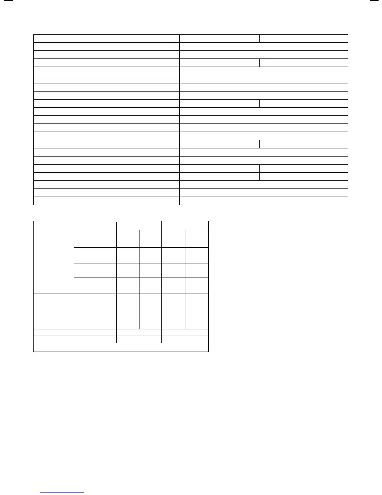
Table 1 - General Data
Note. Gas consumption is calculated using a
caloric value of 38.7 MJ/m
3
(1038 Btu/ft
3
) gross
or 34.9 MJ/m
3
(935 Btu/ft
3
) nett
To obtain the gas consumption at a different
caloric value:
a. For l/s - divide the gross heat input
(kW) by the gross C.V. of the gas (MJ/m
3
)
b. For ft
3
/h - divide the gross heat input (Btu/h)
by the gross C.V. of the gas (Btu/ft
3
)
c. For m
3
/h - multiply l/s by 3.6
Key to symbols
GB = United Kingdom IE = Ireland (Countries of destination)
PMS = Maximum operating pressure of water
C
13
C
33
C
53
= A room sealed appliance designed for connection via ducts to a
horizontal or vertical terminal, which admits fresh air to the burner
and discharges the products of combustion to the outside through
orices which, in this case, are concentric. The fan is up stream of
the combustion chamber.
I
2H
= An appliance designed for use on 2nd Family gas, Group H only.
* The value is used in the UK Government’s Standard Assessment Procedure (SAP) for energy rating of dwellings. The test data from
which it has been calculated have been certied by a notied body.
15 24
MIN MAX MIN MAX
Boiler Input :
Boiler Input ‘Q’ Nett CV kW 4.9 15.1 4.9 24.3
(Btu/h) (16,600) (51,520) (16,600) (82,900)
Gross CV kW 5.4 16.6 5.4 27.0
(Btu/h) (18,400) (56,800) (18,400) (92,000)
Gas Consumption m
3
/h 0.500 1.537 0.500 2.512
(ft
3
/h) (17.8) (54.7) (17.8) (89)
Boiler Output :
Non Condensing kW 4.8 15.0 4.8 24.2
70
o
C Mean Water temp. (Btu/h) (16,500) (51,300) (16,500) (82,600)
Condensing kW 5.1 15.9 5.1 25.6
40
o
C Mean Water temp. (Btu/h) (17,500) (54,250) (17,500) (87,400)
Seasonal efciency* (SEDBUK) 2005 91.1% 91%
Seasonal efciency* (SEDBUK) 2009 89.3% 89.5%
NOx Classication CLASS 5
Table 2 - Performance Data - Central Heating
 Loading...