INSTALLATION
Project Heat - Installation and Servicing
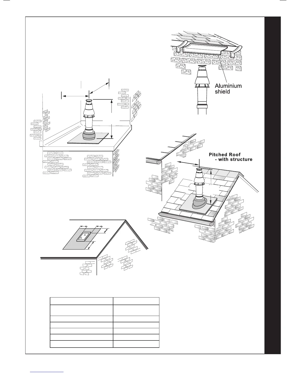
FLUE OUTLET
rf8394-1
690mm
Fixed
300mm
min
30
FLUE TERMINAL POSITION
rf8393-1
300mm
min
300mm
min
625mm
Fixed
Flat roof - with structure
The terminal should be positioned so that products of
combustion can safely disperse at all times.
Pluming may occur at the termination so, where possible,
terminal positions where this could cause a nuisance
should be avoided.
Minimum dimensions are shown below
Terminal Position Minimum Dimension
Directly below an opening,
air brick, windows, etc. 300 mm
Below plastic / painted gutters 300 mm
Painted surface 300 mm
Below eaves or balcony 500 mm
Below velux windows 2000mm
Above or side of velux windows 600mm
RF9807
A
A
B
A
A = 600mm
B = 2000mm
The flue terminal shall not penetrate the shaded area of the roo
f
Note.
The equivalent ue length
resistance of the elbow kits are:
90
o
elbow kit = 1m
45
o
elbow kit = 0.6m
 Loading...