36
INTERNAL INSTALLER WIRING
The Project Heat boiler must be connected to a permanent live supply and NOT
switched by thermostats/programmers.
To install the mains cable:
1. Isolate the mains supply to the boiler.
2. Remove the front panel. Refer to Frame 12.
3. Swing the control box down into the servicing position.
4. Route incoming cable through a grommet in the bottom panel (note that the
grommets are “blind” and will require puncturing) and secure using the clamp and
screws provided in the hardware pack.
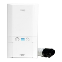
5. Connect the mains cable to the terminal block as shown.
Connecting the Switched Live to the Boiler
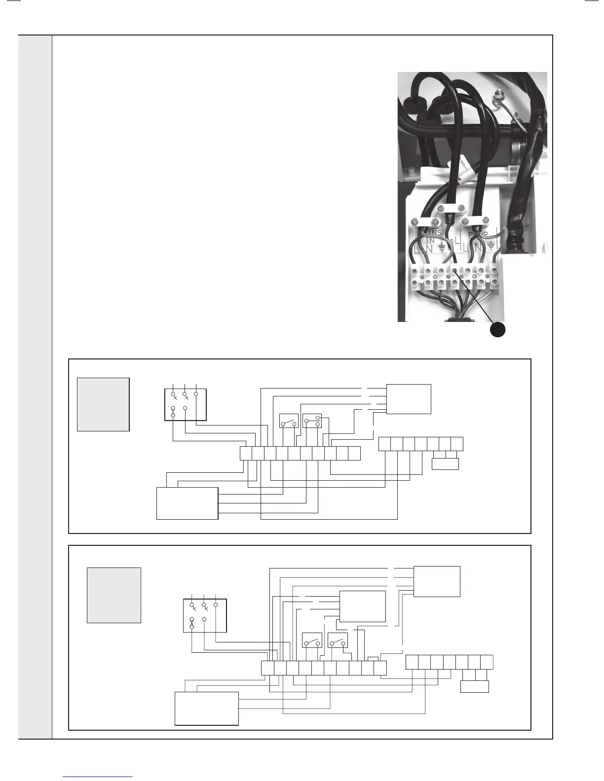
1. Consult the Y Plan and S Plan diagrams below.
2. Isolate the mains supply to the boiler
3. Remove the front panel. Refer to Frame 12.
4. Swing the control box down into the servicing position.
5. Route incoming cable through a grommet in the bottom panel (note that the
grommets are “blind” and will require puncturing) and secure using the clamp and
screws provided in the hardware pack.
6. Connect the switched live to the terminal block as shown.
Frost Thermostat - Wiring
If parts of the system are vulnerable to freezing or the programmer is likely to be left off
during cold weather, a frost stat should be tted in conjunction with a pipe thermostat.
Project Heat BOILER WITH Y PLAN SYSTEM
br
br
o
g/y
b
b
 Loading...