INSTALLATION
Viceroy GT Range - Installation 13
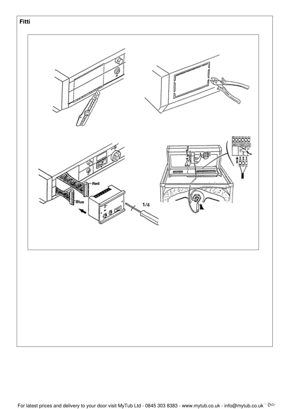
Fitting the SVR option
The SVR option box is to be fitted in the front part of the
control panel. To do this:
1-2. Remove the blank by cutting the surface with a
stanley knife following the black line and by breaking
the perforations in the steel plate behind with a pair of snips.
3. Connect the two connections, situated behind the
blank, to the back of the SVR unit: blue connector to
the blue plug, red connector to the red plug.
4. Locate the unit by its front and fix it using the two
screws sited in the front part of the equipment
(1/4 turn clockwise)
The limit thermostat supplied with the SVR option is to be
fitted in the control panel in the place provided for this
purpose, using the two self tapping screws supplied. The 3
pin thermostat male terminal is to be connected in the
position provided on the 25 pin terminal block after having
taken out the bridge; the thermostat bulb is to be located in
the small pocket in the body of the boiler.
12
34
8219-EN-13
8219-EN-9
8229-EN-45
8219-EN-11
 Loading...