5
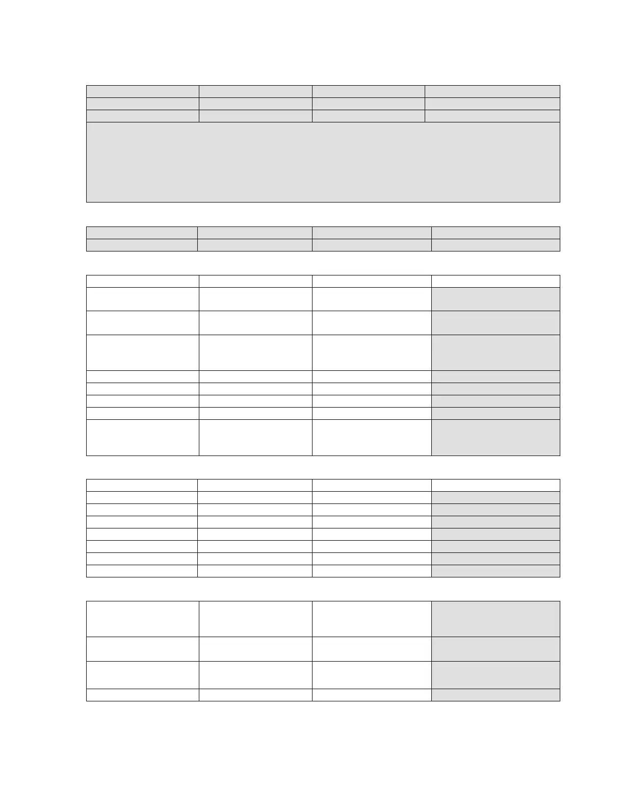
SE INTELLISYS CONTROLLER GENERAL INFORMATION
Date: Customer: Distributor: Technician:
Machine S/N: Model Number Total Hours: Loaded Hours:
NEMA Rating: Starter Type: Ambient Temp: Start-up Date:
Problem Description (What, How, When):
INTELLISYS SE INFORMATION
Intellisys S/N EPROM Version: Offline Pressure: Online Pressure:
Mode of Operation: Options: Comm. Link: Last Alarm:
POWER SUPPLY INFORMATION POWER ON
Circuit Test Point Expected Value Measured Value
Control Transformer
Primary VAC
T1 200-575 VAC
Control Transformer
Secondary : 120 VAC
J5-36 to J5-35 120 VAC +/- 18 VAC
Control Transformer
Secondary : 16 VAC
(center-tap)
J4-30,31
J4-29,30
J4-29,31
16 VAC +/- 2.4 VAC
8 VAC +/- 1.2 VAC
8 VAC +/- 1.2 VAC
Rectified Intellisys DC J4-28,29 10.5 VDC +/- 1.6 VDC
Intellisys Digital 5 VDC J11-1,5 5 VDC +/- .2 VDC
Intellisys Analog 5 VDC J3-25,24 5 VDC +/- .2 VDC
Battery Voltage BAT +/- 3.0 VDC +/- .6 VDC
Ground Fault Current:
Machine running in
loaded condition
Customer Ground
conductor
0.0 Amps AC/DC
+/- .25 Amps AC/DC
see Paragraph 1.3
GROUND RESISTANCE CHECK INFORMATION POWER OFF
Circuit Test Point Expected Value Measured Value
Intellisys Ground J1-1, GND LUG < .5 Ohm
120 VAC Neutral T1, GND Lug < .5 Ohm
Motor Frame Motor chassis, base < .5 Ohm
Sensor Ground 3APT chassis, base < .5 Ohm
Airend Ground Air end chassis, base lug < .5 Ohm
Package Ground Machine Base, GND lug < .5 Ohm
Customer Ground Structural Earth, base lug < .5 Ohm
I/O RESISTANCE CHECK POWER OFF
Pressure
J3 Connected to board
Black to GND
Green to GND
White to GND
<.5 ohm
185 +/- 50
850 ohm +/- 100
Temperature
J2 Connected to board
White to GND 140 ohm +/- 10 @ 77 F
Digital I/O
J1 (a)
N.C.
N.O.
< .5 ohm
> 1 meg ohm
(a) Only test wired contacts and list only connections out of range.

 Loading...