EasyManua.ls Logo

Ingersoll-Rand SSR UP6 40 User Manual

Ingersoll-Rand SSR UP6 40
208 pages
To Next Page IconTo Next Page
To Previous Page IconTo Previous Page
Page #13 background imageLoading...
Page #13 background image
GENERAL INFORMATION
11
SSR UP6 40, SSR UP6 50PE, SSR UP6 50PEI, HF50–PE,
EP50–PE, HP50–PE, HXP50–PE
http://air.ingersollrand.com
38.Condenser, dryer (option)
39.Evaporator, dryer (option)
40.Refrigerant compressor, dryer (option)
41.Hot gas bypass valve, dryer (option)
A Air/Coolant
B Air
C Coolant
D Condensate
E Component boundary
F Refrigerant
G Option

Table of Contents

Question and Answer IconNeed help?

Do you have a question about the Ingersoll-Rand SSR UP6 40 and is the answer not in the manual?
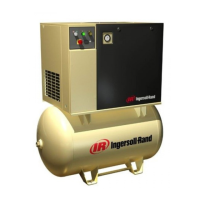
Ingersoll-Rand SSR UP6 40 Specifications

General IconGeneral
ModelSSR UP6 40
TypeRotary Screw Air Compressor
Power40 hp
Pressure125 psig
Phase3
Horsepower40 HP
Maximum Pressure125 psig
Pump TypeRotary Screw
Voltage460V
Air Delivery160 CFM
Noise Level72 dBA

Summary

Safety

Breathing Air Precaution

Ingersoll Rand air compressors are not approved for breathing air.

Operating Instructions - Electro-Pneumatic

Normal and Emergency Stopping

Procedures for stopping the compressor normally or in an emergency.

Operating Instructions - Intellisys Option

Intellisys Control and Instrumentation

Overview of the Intellisys control panel and instrumentation.

Prior to Starting

Pre-operation checks for the Intellisys control system.

Starting

Procedure for starting the compressor with Intellisys control.

Emergency Stop

Procedure for immediate emergency shutdown of the compressor.

Instrument Panel Function

Explanation of Intellisys control panel indicators and buttons.

Controller Warning Messages

Messages displayed for warnings and their interpretation.

Controller Alarms

Messages displayed for critical alarms requiring immediate action.

Maintenance

Trouble Shooting

Related product manuals