Chapter 4 Operation and Display
-37-
Chapter 4 Operation and Display
4.1 Introduction to Operation and Display Interface
Change to the functional parameters, operating status monitoring and running control
(startup, stop) of the inverter can be realized on the operation panel. The outline and functional
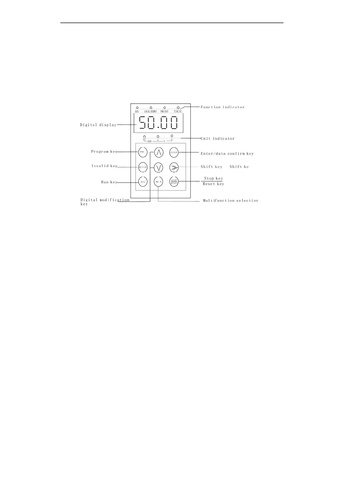
area are shown as Fig.4-1:
Fig.4-1 Operation Panel Diagram
1) Description of Function LED Indictor:
RUN: When it is OFF, it indicates the
inverter is in stop status; when it is ON, it
indicates the inverter is running.
LOCAL/REMOT: For keypad operation,
terminal operation and remote operation
(communication control) LEDs, if the LED is
OFF, It shows the keypad operation control
status; otherwise, it is under the terminal
operation control status.
FWD/REV: It is the LED indictor for
forward/reverse rotation. When it is OFF, it
indicates the inverter is in forward rotation
status; when it is ON, it indicates the inverter
is in reverse rotation status.
TUNE/TC: It is the LED indictor for tuning.
When it is ON it indicates the torque control
status; when it is OFF, it indicates the speed
control status.
2) Unit LED indictor description:
Hz refers to frequency unit.
A refers to current unit.
V refers to voltage unit.
RPM refers to rotation velocity unit.
% refers to percentage
3) Digital display zone:
efesotomasyon.com

 Loading...